Dell PowerEdge 6600 Memory Installation Guidelines (.pdf) - Page 7
Rotate the side release lever down to secure the cover to the side of the microprocessor - fans
 |
View all Dell PowerEdge 6600 manuals
Add to My Manuals
Save this manual to your list of manuals |
Page 7 highlights
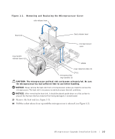
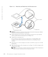
NOTICE: Positioning the microprocessor incorrectly can permanently damage the microprocessor and the system when you turn on the system. When placing the microprocessor in the socket, be sure that all of the pins on the microprocessor go into the corresponding holes. Be careful not to bend the pins. 19 Apply light pressure to the top of the microprocessor while rotating the socket release lever down, securing the microprocessor. 20 Place the new heat sink on top of the microprocessor (see Figure 1-1). 21 Orient the microprocessor cover as shown in Figure 1-1. NOTICE: Failure to properly install the microprocessor cover can permanently damage the microprocessor(s). When installing the microprocessor cover, ensure that the cover retention tabs on the edge of the microprocessor enclosure are inserted into the slots of the cover. 22 Hook the end of the cover over the retention tabs on the edge of the microprocessor enclosure (see Figure 1-1). 23 Swing the microprocessor cover down. 24 Rotate the front release lever down to secure the cover to the front of the microprocessor enclosure (see Figure 1-1). 25 Rotate the side release lever down to secure the cover to the side of the microprocessor enclosure (see Figure 1-1). 26 If you are adding additional microprocessors, install the VRM in the corresponding VRM socket, pushing down firmly to make sure that the ejectors engage (see Figure 1-3). 27 Slide the microprocessor tray into the chassis until the tray stops. 28 Lift the microprocessor tray handles up and push the tray forward slightly to engage the handle clasps. 29 Rotate the microprocessor tray handles down until the tray is secured to the front panel. NOTE: For steps 30 through 33, see your Installation and Troubleshooting Guide for details. 30 Reseat the following components: • Peripheral riser card • Memory riser cards • Fans Microprocessor Upgrade Installation Guide 1-5
-
 1
1 -
 2
2 -
 3
3 -
 4
4 -
 5
5 -
 6
6 -
 7
7 -
 8
8 -
 9
9 -
 10
10 -
 11
11 -
 12
12 -
13
-
14
-
15
-
16
-
17
-
18
-
19
-
20
-
21
-
22
-
23
-
24
-
25
-
26
-
27
-
28
-
29
-
30
-
31
-
32
-
33
-
34
-
35
-
36
-
37
-
38
-
39
-
40
-
41
-
42
-
43
-
44
-
45
-
46
-
47
-
48
-
49
-
50
-
51
-
52
-
53
-
54
-
55
-
56
-
57
-
58
-
59
-
60
-
61
-
62
-
63
-
64
-
65
-
66
 |
 |