Dell PowerEdge 860 Hardware Owner's Manual (PDF) - Page 99
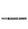
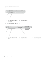
Riser Card Connectors - pcie riser card connectors
 |
View all Dell PowerEdge 860 manuals
Add to My Manuals
Save this manual to your list of manuals |
Page 99 highlights
Table 6-2. System Board Connectors Item Connector 1 PROC 2 12V 3 PWR_CONN 4 DIMM 1 5 DIMM 3 6 DIMM 2 7 DIMM 4 8 FAN 9 BATTERY 10 SATA_0 11 SATA_1 12 PCI FAN 13 FP_CONN1 14 IDE 15 HD_ACT 16 INTRUSION_SWITCH 17 I2C HEADER 18 BMC PROG 19 RISER_CONN1 Description Processor socket power supply connector power supply connector Memory module Memory module Memory module Memory module Power connector for the fans Connector for the 3.0 V coin battery Connector for the SATA 0 hard drive Connector for the SATA 1 hard drive Connector for the PCI fan Control panel interface connector Optical drive interface connector Hard drive activity connector (expansion controller) Connector for the chassis intrusion switch Remote access controller connector Remote access controller connector Riser card interface connector Riser Card Connectors The system is available with either a PCIe riser card or a PCI-X/PCIe riser card. See Figure 6-3 and Figure 6-4 for the location and description of the expansion-card slots on the two riser cards. Jumpers and Connectors 99
-
 1
1 -
2
-
3
-
4
-
5
-
6
-
7
-
8
-
9
-
10
-
11
-
12
-
13
-
14
-
15
-
16
-
17
-
18
-
19
-
20
-
21
-
22
-
23
-
24
-
25
-
26
-
27
-
28
-
29
-
30
-
31
-
32
-
33
-
34
-
35
-
36
-
37
-
38
-
39
-
40
-
41
-
42
-
43
-
44
-
45
-
46
-
47
-
48
-
49
-
50
-
51
-
52
-
53
-
54
-
55
-
56
-
57
-
58
-
59
-
60
-
61
-
62
-
63
-
64
-
65
-
66
-
67
-
68
-
69
-
70
-
71
-
72
-
73
-
74
-
75
-
76
-
77
-
78
-
79
-
80
-
81
-
82
-
83
-
84
-
85
-
86
-
87
-
88
-
89
-
90
-
91
-
92
-
93
-
 94
94 -
 95
95 -
 96
96 -
 97
97 -
 98
98 -
 99
99 -
 100
100 -
 101
101 -
 102
102 -
 103
103 -
 104
104 -
105
-
106
-
107
-
108
-
109
-
110
-
111
-
112
-
113
-
114
-
115
-
116
-
117
-
118
-
119
-
120
-
121
-
122
-
123
-
124
-
125
-
126
-
127
-
128
-
129
-
130
-
131
-
132
-
133
-
134
-
135
-
136
-
137
-
138
-
139
-
140
 |
 |
