Dell PowerEdge C8000 Dell PowerEdge C8220 Hardware Owner's Manual - Page 13
Indicator, Button, or, Connector, Description, On ACPI-compliant operating
 |
View all Dell PowerEdge C8000 manuals
Add to My Manuals
Save this manual to your list of manuals |
Page 13 highlights
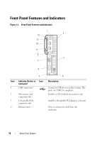
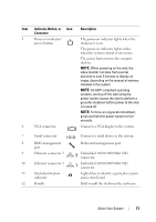
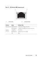
Item Indicator, Button, or Icon Connector 5 Power-on indicator/ power button 6 VGA connector Description The power-on indicator lights when the sled power is on. The power-on indicator lights amber when the system critical event occurs. The power button turns the compute sled on. NOTE: When powering on the sled, the video monitor can take from several seconds to over 2 minutes to display an image, depending on the amount of memory installed in the system. NOTE: On ACPI-compliant operating systems, turning off the sled using the power button causes the sled to perform a graceful shutdown before power to the sled is turned off. NOTE: To force an ungraceful shutdown, press and hold the power button for five seconds. Connects a VGA display to the system. 7 Serial connector 8 BMC management port 9 Ethernet connector 2 10 Ethernet connector 1 11 Sled identification indicator 12 Handle Connects a serial device to the system. Dedicated management port. 2 Embedded 10/100/1000 Mbit NIC connector. 1 Embedded 10/100/1000 Mbit NIC connector. Lights blue to identify a particular system and system board. Hold to pull the sled from the enclosure. About Your System 13
-
 1
1 -
2
-
3
-
4
-
5
-
6
-
7
-
 8
8 -
 9
9 -
 10
10 -
 11
11 -
 12
12 -
 13
13 -
 14
14 -
 15
15 -
 16
16 -
 17
17 -
 18
18 -
19
-
20
-
21
-
22
-
23
-
24
-
25
-
26
-
27
-
28
-
29
-
30
-
31
-
32
-
33
-
34
-
35
-
36
-
37
-
38
-
39
-
40
-
41
-
42
-
43
-
44
-
45
-
46
-
47
-
48
-
49
-
50
-
51
-
52
-
53
-
54
-
55
-
56
-
57
-
58
-
59
-
60
-
61
-
62
-
63
-
64
-
65
-
66
-
67
-
68
-
69
-
70
-
71
-
72
-
73
-
74
-
75
-
76
-
77
-
78
-
79
-
80
-
81
-
82
-
83
-
84
-
85
-
86
-
87
-
88
-
89
-
90
-
91
-
92
-
93
-
94
-
95
-
96
-
97
-
98
-
99
-
100
-
101
-
102
-
103
-
104
-
105
-
106
-
107
-
108
-
109
-
110
-
111
-
112
-
113
-
114
-
115
-
116
-
117
-
118
-
119
-
120
-
121
-
122
-
123
-
124
-
125
-
126
-
127
-
128
-
129
-
130
-
131
-
132
-
133
-
134
-
135
-
136
-
137
-
138
-
139
-
140
-
141
-
142
-
143
-
144
-
145
-
146
-
147
-
148
-
149
-
150
-
151
-
152
-
153
-
154
-
155
-
156
-
157
-
158
-
159
-
160
-
161
-
162
-
163
-
164
-
165
-
166
-
167
-
168
-
169
-
170
-
171
-
172
-
173
-
174
-
175
-
176
-
177
-
178
-
179
-
180
-
181
-
182
-
183
-
184
-
185
-
186
-
187
-
188
-
189
-
190
-
191
-
192
-
193
-
194
-
195
-
196
-
197
-
198
-
199
-
200
-
201
-
202
-
203
-
204
-
205
-
206
-
207
-
208
 |
 |