Dell PowerEdge FX2 Dell PowerEdge FN I/O Aggregator Getting Started Guide - Page 6
USB Console Port, System Status, USB Ports on Front Panel
 |
View all Dell PowerEdge FX2 manuals
Add to My Manuals
Save this manual to your list of manuals |
Page 6 highlights
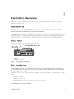
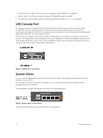
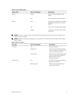
• Ports 9 and 10 are Fibre Channel (FC) type and support eight Gigabit FC, by default. • Ports 11 and 12 are Ethernet type and support 10 Gigabit Ethernet, by default. • You can also convert ports 9 and 10 to Ethernet type by using the port mode command. USB Console Port To manage the switch through an RS-232 serial interface, use the upper universal serial bus (USB) console port. This port provides a direct connection to the switch and allows you to access the command-line interface (CLI) from a console terminal connected to the port through the provided serial cable (with USB UART-A to back-plane to CMC). The console port supports asynchronous data of eight data bits, one stop bit, no parity bit, and no flow control. The default baud rate is 115,200 bps. The lower USB port (in the following figure) functions as an external flash drive that you can use to store configuration files, load new images, and import or export scripts or report files used in virtualization applications. Figure 2. USB Ports on Front Panel System Status You can view the Aggregator status information in several ways, including light emitting diodes (LEDs) and boot menu options. You can also view status information through the show commands and with the simple network management protocol (SNMP). The Aggregator includes LED displays as shown in the following figure: Figure 3. System LED s on Front Panel The following table lists the LED definitions for the Aggregator. 6 Hardware Overview
-
 1
1 -
 2
2 -
 3
3 -
 4
4 -
 5
5 -
 6
6 -
 7
7 -
 8
8 -
 9
9 -
 10
10 -
 11
11 -
 12
12 -
13
 |
 |
