Dell PowerEdge FX2 Dell PowerEdge FN I/O Aggregator Installation Guide - Page 10
Power Supplies, Fans, Port Numbering, System Status - enclosure
 |
View all Dell PowerEdge FX2 manuals
Add to My Manuals
Save this manual to your list of manuals |
Page 10 highlights
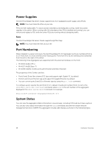
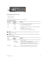
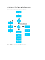
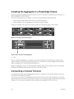
Power Supplies The Dell PowerEdge FX2 server chassis supports two hot-swappable power supply units (PSUs). NOTE: You must install the PSUs at your site. PSUs are field-replaceable. To ensure power redundancy and adequate cooling, install two power supplies in the switch. When running with full redundancy (two PSUs installed and running), you can remove and replace a PSU while the other PSUs are running without disrupting traffic. Fans The Dell PowerEdge FX2 server chassis supports eight fan trays. NOTE: You must install the fans at your site. Port Numbering When installed in a server enclosure, the Dell PowerEdge FN I/O Aggregator ports are numbered from 1 to 12. Ports from 1 to 8 are internal server-facing ports. Ports from 9 to 12 are external ports numbered from the left to the right of the switch. The following three Aggregators are supported with the external interfaces on the front: • FN 410S (4x10G SFP+) • FN 410T (4x10G Base-T) • FN 2210S (4x10G Combo ports with Ethernet and Fibre Channel) The properties of the Combo card are: • Ports 9 and 10 are fibre channel (FC) type and support eight Gigabit FC, by default. • Ports 11 and 12 are Ethernet type and support 10 Gigabit Ethernet, by default. • You can convert ports 9 and 10 to Ethernet type by using the port mode command. To configure a port, specify the slot (from 0 to 5; default: 0) and port number (from 1 to 12) in the interface port-type slot/port command, where slot is the unit number of the aggregator displayed in the show system brief command. For example: Dell(conf)# interface tengigabitethernet 0/4 System Status You can view the aggregator status information in several ways, including LEDs and boot menu options. You can also view status information through the show commands and with the simple network management protocol (SNMP).The aggregator includes LED displays as shown in the following figure. 10 Hardware Overview
-
 1
1 -
2
-
3
-
4
-
 5
5 -
 6
6 -
 7
7 -
 8
8 -
 9
9 -
 10
10 -
 11
11 -
 12
12 -
 13
13 -
 14
14 -
 15
15 -
16
-
17
-
18
-
19
-
20
-
21
-
22
-
23
-
24
 |
 |