Dell PowerEdge FX2 Dell PowerEdge FN I/O Aggregator Installation Guide - Page 15
Auto-Configuration, Dell Chassis Management Controller CMC User's Guide, Dell Networking Configuration
 |
View all Dell PowerEdge FX2 manuals
Add to My Manuals
Save this manual to your list of manuals |
Page 15 highlights
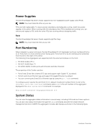
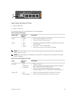
To use the console port, you will need the following equipment: • VT100-compatible terminal, or a desktop, or a portable computer with a serial port running VT100 terminal emulation software, such as Microsoft HyperTerminal. • A serial cable (provided) with a USB type-A connector for the console port and DB-9 connector for the terminal. To connect a terminal to the switch console port, perform the following tasks: 1. Connect the DB-9 connector on the serial cable to the terminal or computer running VT100 terminal emulation software. 2. Configure the terminal emulation software as follows: a. Select the appropriate serial port (for example, COM 1) to connect to the console. b. Set the data rate to 115200 baud. c. Set the data format to 8 data bits, 1 stop bit, and no parity. d. Set the flow control to none. e. Set the terminal emulation mode to VT100. f. Select Terminal keys for Function, Arrow, and Ctrl keys. Ensure that the setting is for Terminal keys (not Microsoft Windows keys). The default enable password is calvin. 3. Connect the USB connector on the cable directly to the switch console port. The console port is located on the left side of the front end ports. For information about how to access the CMC to configure the Dell PowerEdge FN I/O Aggregator, refer to the Dell Chassis Management Controller (CMC) User's Guide on the Dell Support website at http:// www.dell.com/support/manuals. The CMC online help provides information about how to use the Web interface. For more information about the Aggregator configuration, refer to the Dell Networking Configuration Guide for the Dell PowerEdge FN I/O Aggregator. Auto-Configuration After the Aggregator powers on, it auto-configures and is operational with the following software features enabled: • VLANs: In Standalone mode, all ports are configured as members of all VLANs (4094). All VLANs are up and can send or receive Layer 2 traffic. • Data center bridging capability exchange protocol (DCBX). • Fiber Channel over Ethernet (FCoE) connectivity. • FCoE initiation protocol (FIP) snooping. • Hybrid ports: Ports are administratively up and auto-configured to operate as hybrid ports to transmit tagged and untagged VLAN traffic. • Internet small computer system interface (iSCSI) optimization. • Internet group management protocol (IGMP) snooping. • Jumbo frames: Ports are set to a maximum transmission unit (MTU) of 12,000 bytes. • Link aggregation: All uplink ports are configured in a single link aggregation group (LAG) (LAG 128). • Link layer discovery protocol (LLDP): Enabled on all ports. Installation 15
-
 1
1 -
2
-
3
-
4
-
5
-
6
-
7
-
8
-
9
-
 10
10 -
 11
11 -
 12
12 -
 13
13 -
 14
14 -
 15
15 -
 16
16 -
 17
17 -
 18
18 -
 19
19 -
 20
20 -
21
-
22
-
23
-
24
 |
 |