Dell PowerEdge FX2 Dell PowerEdge FN I/O Aggregator Installation Guide - Page 14
Installing the Aggregator in a PowerEdge Chassis, Connecting a Console Terminal - blade chassis
 |
View all Dell PowerEdge FX2 manuals
Add to My Manuals
Save this manual to your list of manuals |
Page 14 highlights
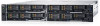
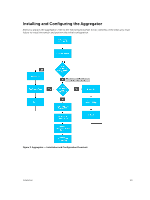
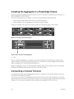
Installing the Aggregator in a PowerEdge Chassis After you unpack the aggregator, slide the switch into one of the open I/O module slots in the back of a Dell PowerEdge FX2 server chassis. The Dell PowerEdge FX2 server chassis is a 2U rack-mountable blade chassis that holds: • Server modules: Eight quarter-width sleds or four half-width sleds. • Switch modules: Two I/O aggregators or two pass-through modules. Install server blades in the front of the chassis; install I/O modules in the back of the chassis. Figure 4. Front View with Server Modules Figure 5. Back View with Two Aggregators 1 - CMC After you slide the aggregator in so that the connectors on the back of the blade are inserted into the chassis midplane, the switch automatically powers on. The CMC in the chassis validates that the switch blade is a supported I/O module before powering it on. When the aggregator powers on, the bootloader loads the image in the local flash memory. The image initializes the hardware and brings the switch up in operational mode. Connecting a Console Terminal To configure the switch, after the aggregator powers on, complete all the external cabling connections and connect a terminal to the switch. To monitor and configure the aggregator with the serial console, use the USB console port on the front panel of the switch to connect it to a VT100 terminal or to a computer running VT100 terminal emulation software. The console port is implemented as a data terminal equipment (DTE) connector. 14 Installation
-
 1
1 -
2
-
3
-
4
-
5
-
6
-
7
-
8
-
 9
9 -
 10
10 -
 11
11 -
 12
12 -
 13
13 -
 14
14 -
 15
15 -
 16
16 -
 17
17 -
 18
18 -
 19
19 -
20
-
21
-
22
-
23
-
24
 |
 |
