Cabling the Dell™ PowerEdge™ R610
Page 1
Table of Contents
Introduction
...............................................................................................................................................................
2
Cabling a PowerEdge R610 with CMA
.......................................................................................................................
2
2.1 Installing the Cables to the System
..........................................................................................................
2
Figure 1: System with Cables Installed
.....................................................................................................
2
2.2 Route the Power Cables through the Strain Reliefs
..................................................................................
3
Figure 2: Routing Power Cables through the Strain Reliefs
....................................................................
3
2.3 Routing the Cables through the CMA
........................................................................................................
3
Figure 3: Routing the Cables through the CMA
.......................................................................................
4
Figure 4: Attaching the KVM Dongle to the CMA Basket
.........................................................................
4
Figure 5: Completed Left Side Mounted CMA Installation
.......................................................................
5
Figure 6: Completed Right Side Mounted CMA Installation
....................................................................
5
Cabling a PowerEdge R610 without a CMA
...............................................................................................................
6
3.1 Routing the Cables
....................................................................................................................................
6
Figure 7: Cable Routing Without a CMA
..................................................................................................
6
3.1 Removing the CMA Brackets for Shallow Racks
........................................................................................
6
Figure 8: Removing the CMA Brackets for Shallow Racks
........................................................................
6
Replacing a Power Supply on a PowerEdge R610 with CMA
.....................................................................................
7
Figure 9: Replacing Outer Power Supply
..................................................................................................
7
Cabling a PowerEdge R610 Installed in Static Rails
...................................................................................................
8
Figure 10: Cabling a System Installed in Static Rails
................................................................................
8
 1
1 2
2 3
3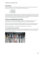 4
4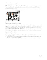 5
5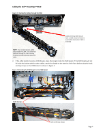 6
6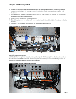 7
7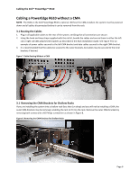 8
8 9
9

