Dell PowerEdge PDU Metered LCD Cabling PowerEdge R610 - Page 8
Cabling a PowerEdge R610 without a CMA
 |
View all Dell PowerEdge PDU Metered LCD manuals
Add to My Manuals
Save this manual to your list of manuals |
Page 8 highlights
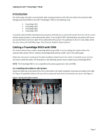
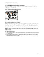
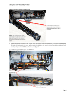
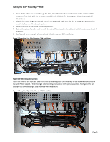
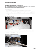
Cabling the Dell™ PowerEdge™ R610 Cabling a PowerEdge R610 without a CMA NOTE: The CMA on the Dell PowerEdge R610 is optional. Without the CMA installed, the system must be powered down and all cables disconnected before it can be removed from the rack. 3.1 Routing the Cables 1. Plug in all applicable cables to the rear of the system, verifying that all connections are secure. 2. Using the hook and loop straps supplied with the rail kit, bundle the cables and secure them to either the left rail or right rail CMA attachment brackets as described in the Rack Installation Guide. See Figure 7 for an example of power cables secured to the left CMA bracket and data cables secured to the right CMA bracket. 3. It is recommended that the cables be secured to the outer brackets, but cables may be secured to the inner brackets if desired. Figure 7: Cable Routing Without a CMA 3.1 Removing the CMA Brackets for Shallow Racks If you are installing the system into a shallow rack (less than 1m deep) and you will not be installing a CMA, the outer CMA brackets may be removed, enabling the rails to fit into the rack. Remove the outer CMA brackets by removing both screws with a #2 Philips screwdriver as shown in Figure 8. Figure 8: Removing the CMA Brackets for Shallow Racks Page 6
-
 1
1 -
2
-
 3
3 -
 4
4 -
 5
5 -
 6
6 -
 7
7 -
 8
8 -
 9
9 -
 10
10
 |
 |
