Dell PowerVault MD3260 Owner's Manual - Page 18
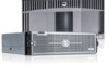
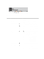
MD3660f Fibre Channel RAID Controller Module Features And Indicators
 |
View all Dell PowerVault MD3260 manuals
Add to My Manuals
Save this manual to your list of manuals |
Page 18 highlights
Item Indicator, Button, or Icon Connector 5 Cache active or cache offload indicator 6 System identification indicator 7 Controller fault indicator 8 Controller power indicator 9 SAS OUT port 10 iSCSI IN port 0 iSCSI IN port 1 Description The cache active or cache offload indicator lights green when on-board controller memory contains data. If AC power fails, this LED changes to indicate cache offload status. If the password reset function has successfully changed the password, this LED flashes on and off briefly. The system identification indicator blinks blue when system identification switch push-button on the enclosure front panel is pressed. The controller fault indicator lights amber when controller fault is detected. The controller power indicator lights green when controller power is on. Provides SAS connection for cabling to a downchain expansion enclosure. Provides host-to-controller iSCSI 1/10 Gbps Ethernet connection. MD3660f Fibre Channel RAID Controller Module Features And Indicators Figure 11. MD3660f Fibre Channel RAID Controller Module Features and Indicators Item Indicator, Button, or Icon Connector 1 Serial debug port 2 Ethernet management port 3 Password reset switch 4 Battery fault indicator Description Dell support only. Provides a 100/1000 Mbps Ethernet connection for out-of-band management of the enclosure. Pressing this switch resets the password. The battery fault indicator lights amber when battery backup unit or battery has failed. 18
-
 1
1 -
2
-
3
-
4
-
5
-
6
-
7
-
8
-
9
-
10
-
11
-
12
-
 13
13 -
 14
14 -
 15
15 -
 16
16 -
 17
17 -
 18
18 -
 19
19 -
 20
20 -
 21
21 -
 22
22 -
 23
23 -
24
-
25
-
26
-
27
-
28
-
29
-
30
-
31
-
32
-
33
-
34
-
35
-
36
-
37
-
38
-
39
-
40
-
41
-
42
-
43
-
44
-
45
-
46
-
47
-
48
-
49
-
50
-
51
-
52
-
53
-
54
-
55
-
56
-
57
-
58
 |
 |
