Dell Precision 530 Service Manual - Page 74
EIDE Device Installation Guidelines - support
 |
View all Dell Precision 530 manuals
Add to My Manuals
Save this manual to your list of manuals |
Page 74 highlights
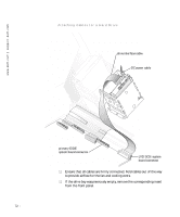
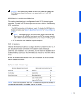
www.dell.com | support.dell.com EIDE Device Installation Guidelines Jumper Settings All EIDE drives should be configured for the Cable Select jumper position, which assigns master and slave status to drives by their position on the interface cable. When two EIDE drives are connected to a single EIDE interface cable and are configured for the Cable Select jumper position, the drive attached to the last connector on the interface cable is the master, or boot device (drive 0), and the device attached to the middle connector on the interface cable is the slave device (drive 1). Refer to the documentation in your drive upgrade kit for information on setting devices to the Cable Select jumper position. General Guidelines With the two EIDE interface connectors on the system board, your computer can support up to four EIDE drives: • The primary EIDE system-board connector should be cabled to EIDE hard drives • The secondary EIDE connector should be cabled to EIDE CD, DVD, tape, DAT, and zip drives To locate the EIDE interface connectors on the system board, see "System Board Components" or "Interior Service Label." Each EIDE interface connector on the system board supports the following: • Two devices, master and slave • LBA • PIO Mode 3 and Mode 4 • Ultra ATA/100 (backward-compatible with ATA/66 and ATA/33) EIDE Cables To transfer data at full speed, Ultra ATA/100 hard drives require an 80conductor cable like that used with ATA/66 drives. The 80-conductor cable has a 40-pin connector like the ATA/33 cable, but it has twice as many wires within the cable. If you use an ATA/33 cable with Ultra ATA/100 hard drives, the drives will operate properly, but data will transfer at ATA/33 speeds. 74
-
 1
1 -
2
-
3
-
4
-
5
-
6
-
7
-
8
-
9
-
10
-
11
-
12
-
13
-
14
-
15
-
16
-
17
-
18
-
19
-
20
-
21
-
22
-
23
-
24
-
25
-
26
-
27
-
28
-
29
-
30
-
31
-
32
-
33
-
34
-
35
-
36
-
37
-
38
-
39
-
40
-
41
-
42
-
43
-
44
-
45
-
46
-
47
-
48
-
49
-
50
-
51
-
52
-
53
-
54
-
55
-
56
-
57
-
58
-
59
-
60
-
61
-
62
-
63
-
64
-
65
-
66
-
67
-
68
-
 69
69 -
 70
70 -
 71
71 -
 72
72 -
 73
73 -
 74
74 -
 75
75 -
 76
76 -
 77
77 -
 78
78 -
 79
79 -
80
-
81
-
82
-
83
-
84
-
85
-
86
-
87
-
88
-
89
-
90
-
91
-
92
-
93
-
94
-
95
-
96
-
97
-
98
-
99
-
100
-
101
-
102
-
103
-
104
-
105
-
106
-
107
-
108
-
109
-
110
-
111
-
112
-
113
-
114
-
115
-
116
-
117
-
118
-
119
-
120
-
121
-
122
-
123
-
124
-
125
-
126
 |
 |
