Dell S5212F-ON EMC PowerSwitch S5200F-ON Series Installation Guide February 20 - Page 27
S5200F-ON Series switch installation, S5232F-ON NEBS compliance, Important information
 |
View all Dell S5212F-ON manuals
Add to My Manuals
Save this manual to your list of manuals |
Page 27 highlights
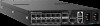
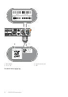
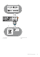
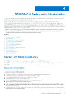
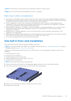
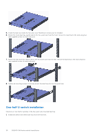
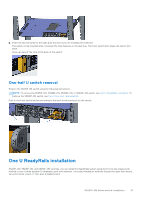
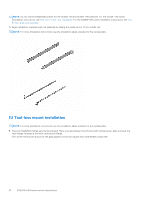
4 S5200F-ON Series switch installation To install the S5200F-ON Series (S5232F-ON, S5248F-ON, S5296F-ON, S5224F-ON, and S5212F-ON) switch, complete the installation procedures in the order presented in this chapter. Always handle the switch and components with care. Avoid dropping the switch or its field replaceable units (FRUs). For the S5212F-ON switch installation instructions, see One-half U front-rack installation. For the S5224F-ON, S5248F-ON, and S5232F-ON switches, you can install the ReadyRails system. Due to the chassis weight, the S5296F-ON switch does not support a two-post rack installation; you must install the S5296F-ON in a four-post rack. For the S5296F-ON switch installation instructions, see S5296F-ON four-post rack assembly. NOTE: ESD damage can occur if components are mishandled. Always wear an ESD-preventive wrist or heel ground strap when handling the S5200F-ON Series switch and components. As with all electrical devices of this type, take all the necessary safety precautions to prevent injury when installing this switch. Topics: • S5232F-ON NEBS compliance • Ground cable • Rack or cabinet hardware installation • One-half U front-rack installation • One U ReadyRails installation • Two U four-post rack assembly • DC power connections • S5212F-ON only DC power connections • Optics installation • Switch start up • After switch placement • Switch replacement S5232F-ON NEBS compliance The S5232F-ON switch qualifies as network equipment building system-3 (NEBS-3) compliant. To be NEBS-compliant, orient your switch in the rack so that the air inlet is from the front aisle and the air exhaust is to the back aisle. Important information WARNING: To be NEBS-compliant: ● Locate your switch in a restricted-access area were only trained personnel are allowed access. ● Install and connect your switch to the common bonding network (CBN). ● You can also install and connect your switch to the central office. ● Connect the battery returns of your switch as DC-I. ● Use a shielded and grounded cable at both ends of the management port. ● Ground your switch using a copper ground conductor. ● Clean and coat all bare grounding connection points on your switch with an antioxidant solution before making connections. ● Bring all unplated ground connection surfaces on your switch to a bright finish and treat them with an antioxidant solution before making connections. ● To ensure electrical continuity, remove any nonconductive surfaces from the ground connection points and threaded holes that are used to secure the ground lugs. S5200F-ON Series switch installation 27
-
 1
1 -
2
-
3
-
4
-
5
-
6
-
7
-
8
-
9
-
10
-
11
-
12
-
13
-
14
-
15
-
16
-
17
-
18
-
19
-
20
-
21
-
 22
22 -
 23
23 -
 24
24 -
 25
25 -
 26
26 -
 27
27 -
 28
28 -
 29
29 -
 30
30 -
 31
31 -
 32
32 -
33
-
34
-
35
-
36
-
37
-
38
-
39
-
40
-
41
-
42
-
43
-
44
-
45
-
46
-
47
-
48
-
49
-
50
-
51
-
52
-
53
-
54
-
55
-
56
-
57
-
58
-
59
-
60
-
61
-
62
-
63
-
64
 |
 |