Dell S5212F-ON EMC PowerSwitch S5200F-ON Series Installation Guide February 20 - Page 28
Ground cable, Rack or cabinet hardware installation
 |
View all Dell S5212F-ON manuals
Add to My Manuals
Save this manual to your list of manuals |
Page 28 highlights
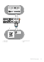
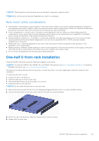
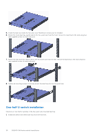
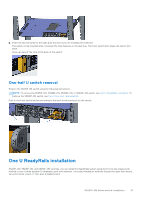
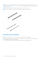
● Use the two-hole, Listed, compression-type lug with an AWG 14 gauge wire for switch grounding. ● Dell Technologies recommends changing the front air filter every three months, depending on the switch environment (if applicable). NOTE: If you install and connect the switches to a commercial AC power source, you must connect the switch to an external surge protection device (SPD). NOTE: The intrabuilding ports of the equipment or subassembly are suitable for connection to intrabuilding or unexposed wiring or cabling-only of the intrabuilding port(s) of the equipment or subassembly. The intrabuilding ports must not be metallically connected to interfaces that connect to the OSP or its wiring. These interfaces are designed for use as intrabuilding interfaces only (Type 4 or 4a ports as described in GR-1089: Electromagnetic Compatibility and Electrical Safety) and require isolation from the exposed OSP cabling with the addition of primary protectors. NOTE: The S5232F-ON switch can operate at -40 VDC to -60 VDC at a maximum current level of 15A. NOTE: The S5232F-ON switch is Earthquake Z4-compliant when you attach the rails to the frame using threaded hardware. Ground cable To attach a ground cable to the switch, use the included M4 screws. NOTE: For an AC-powered switch, although the third conductor of the AC power cord provides a ground path, Dell EMC recommends grounding your switch with a dedicated ground wire. You can order an AC ground lug separately. NOTE: For a DC-powered switch, the only way to safely ground your switch is to attach a dedicated ground wire. The ground lug kit ships in a plastic bag placed with the other accessories inside the shipping box. The ground lug bracket screws ship attached to the switch. Before you install the DC switch in the dual-tray, attach the ground lug and bracket to the switch using the included screws and then attach the DC ground wire to the ground lug. The ground cable is not included. The grounding lugs must be a UL-recognized, crimp-type lug. CAUTION: Grounding conductors must be made of copper. Do not use aluminum conductors. NOTE: Coat the one-hole lug with an anti-oxidant compound before crimping. Also, bring any unplated mating surfaces to a shiny finish and coat with an anti-oxidant before mating. Plated mating surfaces must be clean and free from contamination. NOTE: The rack installation ears are not suitable for grounding. To connect the ground cable to the switch: 1. Cut your user-supplied ground cable to the desired length. The cable length must facilitate proper operation of the fault interrupt circuits. Use the shortest cable route allowable. 2. Crimp the ground cable inside the pre-installed ground lug. 3. Attach the other end of the ground cable to a suitable ground point such as the rack or cabinet. The rack installation ears are not a suitable grounding point. Rack or cabinet hardware installation You may either place the switch on a rack shelf or mount the switch directly into a 19" wide, EIA-310- E-compliant rack. Rack mounting for the S5232F-ON, S5248F-ON, and S5224F-ON switches includes four-post, two-post, round threaded holes, or square holes. The ReadyRails system is provided for 1U front-rack and two-post installations. Do not use the ReadyRails system for the S5296F-ON or S5212F-ON switches. For the S5212F-ON switch, see One-half U front-rack installation. For the S5296F-ON switch, see Two U four-post rack assembly. The ReadyRails system includes separately packaged rail assemblies. WARNING: This document is a condensed reference. Read the safety instructions in your Safety, Environmental, and Regulatory information booklet before you begin. 28 S5200F-ON Series switch installation
-
 1
1 -
2
-
3
-
4
-
5
-
6
-
7
-
8
-
9
-
10
-
11
-
12
-
13
-
14
-
15
-
16
-
17
-
18
-
19
-
20
-
21
-
22
-
 23
23 -
 24
24 -
 25
25 -
 26
26 -
 27
27 -
 28
28 -
 29
29 -
 30
30 -
 31
31 -
 32
32 -
 33
33 -
34
-
35
-
36
-
37
-
38
-
39
-
40
-
41
-
42
-
43
-
44
-
45
-
46
-
47
-
48
-
49
-
50
-
51
-
52
-
53
-
54
-
55
-
56
-
57
-
58
-
59
-
60
-
61
-
62
-
63
-
64
 |
 |
