Dell Vostro 2521 Dell Vostro 2521 Owner's Manual - Page 18
Installing the Palmrest, Removing the Input/Output (I/O) Board
 |
View all Dell Vostro 2521 manuals
Add to My Manuals
Save this manual to your list of manuals |
Page 18 highlights
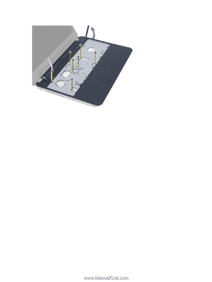
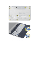
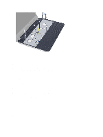
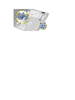
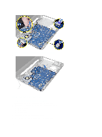
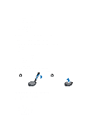
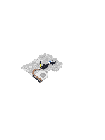
Installing the Palmrest 1. Align and press the plamrest on the computer until it snap into place at all sides. 2. Connect the touchpad cable and the power-button cables to the system board. 3. Tighten the screws to secure the palmrest to the system board. 4. Flip the computer and tighten the screws to secure the palmrest to the computer. 5. Install: a) keyboard b) optical-drive assembly c) memory module d) access panel e) battery 6. Follow the procedures in After Working Inside Your Computer. Removing the Input/Output (I/O) Board 1. Follow the procedures in Before Working Inside Your Computer. 2. Remove: a) battery b) access panel c) keyboard d) palmrest 3. Disconnect the I/O cable from the system board. 4. Remove the screw that secures the I/O board to the computer and lift the I/O board from the computer. 18
-
 1
1 -
2
-
3
-
4
-
5
-
6
-
7
-
8
-
9
-
10
-
11
-
12
-
 13
13 -
 14
14 -
 15
15 -
 16
16 -
 17
17 -
 18
18 -
 19
19 -
 20
20 -
 21
21 -
 22
22 -
 23
23 -
24
-
25
-
26
-
27
-
28
-
29
-
30
-
31
-
32
-
33
-
34
-
35
-
36
-
37
-
38
-
39
-
40
-
41
-
42
-
43
-
44
-
45
-
46
-
47
-
48
-
49
-
50
-
51
-
52
-
53
 |
 |