Dell Vostro 2521 Dell Vostro 2521 Owner's Manual - Page 25
Installing the Speakers, Removing the Display Assembly
 |
View all Dell Vostro 2521 manuals
Add to My Manuals
Save this manual to your list of manuals |
Page 25 highlights
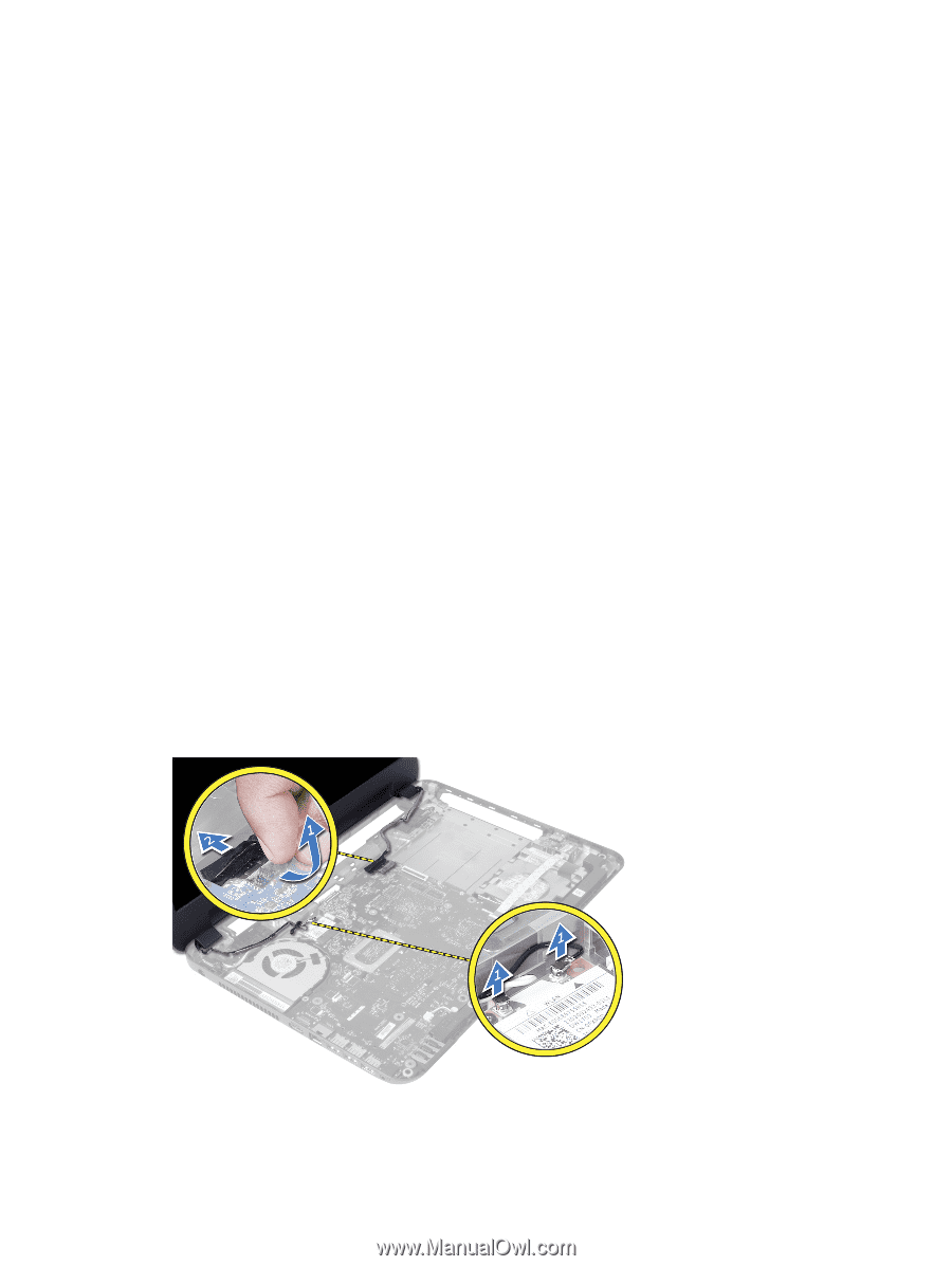
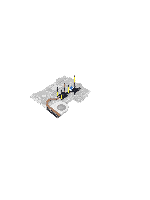
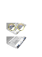
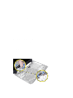
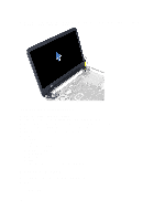
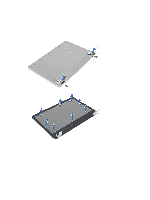
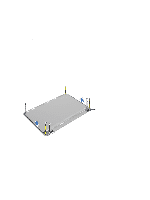
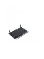
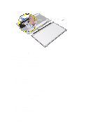
Installing the Speakers 1. Place the speaker assembly in its slot and route the cables through the channels. 2. Replace the LED silicon tubes to the computer. 3. Affix the tape that secures the LED silicon tubes to the computer. 4. Install: a) system board b) wireless mini-card c) palmrest d) keyboard e) optical-drive assembly f) hard-drive assembly g) memory module h) access panel i) battery 5. Follow the procedures in After Working Inside Your Computer. Removing the Display Assembly 1. Follow the procedures in Before Working Inside Your Computer. 2. Remove: a) battery b) access panel c) memory module d) hard-drive assembly e) optical-drive assembly f) keyboard g) palmrest 3. Peel the tape that secures the LVDS and camera cables to the system board and disconnect them from connector on the system board. Disconnect the wireless-mini card antennae from the connector on the system board. 25
-
 1
1 -
2
-
3
-
4
-
5
-
6
-
7
-
8
-
9
-
10
-
11
-
12
-
13
-
14
-
15
-
16
-
17
-
18
-
19
-
 20
20 -
 21
21 -
 22
22 -
 23
23 -
 24
24 -
 25
25 -
 26
26 -
 27
27 -
 28
28 -
 29
29 -
 30
30 -
31
-
32
-
33
-
34
-
35
-
36
-
37
-
38
-
39
-
40
-
41
-
42
-
43
-
44
-
45
-
46
-
47
-
48
-
49
-
50
-
51
-
52
-
53
 |
 |