Dell Vostro 3500 Service Manual - Page 21
Remove the screws that secure the display assembly to the computer., Lift the display assembly up
 |
View all Dell Vostro 3500 manuals
Add to My Manuals
Save this manual to your list of manuals |
Page 21 highlights
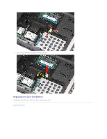
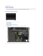
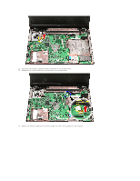
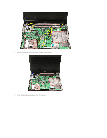
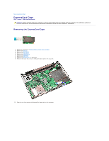
15. Remove the screws that secure the display assembly to the computer. 16. Lift the display assembly up and away from the computer.
-
 1
1 -
2
-
3
-
4
-
5
-
6
-
7
-
8
-
9
-
10
-
11
-
12
-
13
-
14
-
15
-
 16
16 -
 17
17 -
 18
18 -
 19
19 -
 20
20 -
 21
21 -
 22
22 -
 23
23 -
 24
24 -
 25
25 -
 26
26 -
27
-
28
-
29
-
30
-
31
-
32
-
33
-
34
-
35
-
36
-
37
-
38
-
39
-
40
-
41
-
42
-
43
-
44
-
45
-
46
-
47
-
48
-
49
-
50
-
51
-
52
-
53
-
54
-
55
-
56
-
57
-
58
-
59
-
60
-
61
-
62
-
63
-
64
-
65
-
66
-
67
-
68
-
69
-
70
-
71
-
72
-
73
-
74
-
75
-
76
-
77
-
78
-
79
 |
 |

15.
Remove the screws that secure the display assembly to the computer.
16.
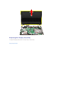
Lift the display assembly up and away from the computer.