Denon DN-C635 Operating Instructions - Page 8
Connections, Ext. Sync. - cd
 |
UPC - 081757505376
View all Denon DN-C635 manuals
Add to My Manuals
Save this manual to your list of manuals |
Page 8 highlights
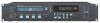
ENGLISH NOTE: The tally output pin has open collector IC specifications (Imax. 20 mA, Vmax. 3.3 V), but the maximum supply current is 80 mA, so use with a total load current of 80 mA or less. u External synchronized control jacks (EXT. SYNC.) • Connect these for synchronized recording. i Cascade control jacks (CASCADE) • Connect these for continuous operation on multiple units. • When the cascade mode is set to "ON", the start signal is output from this output jack once operation is finished. (Preset function) (3) Display q CD transport indicator w Mode display portion FILE : This lights when the file name of MP3 is displayed. FOLDER : This lights in the folder selection mode. TITLE : This lights when the title in the MP3 ID3-Tag or CD Text is displayed. MP3 : This lights when a disc containing MP3 format file is loaded. PROG : This lights in the program mode. REPEAT, 1 : This lights in the repeat mode. CASCADE : This lights in the cascade mode. (Preset function) ALBUM : This lights when the album name in the MP3 ID3-Tag is displayed. ARTIST : This lights when the artist name in the MP3 ID3-Tag is displayed. e CD pitch display r Playing position display • This indicates the current position within the track's totalplaying time. • In the MP3 play mode, it may be unable to display correctly. t 20 tracks music calender • In the single track play mode, only the specified track lights. • In the continuous play mode, everything from the specified track to the last track lights. • Track numbers are displayed up to track 20. Track 21 and on are not displayed. • MP3 is not displayed. y Multiple display • This displays Track No. of CD, playing time of CD, various operational information, text message, etc. u Time mode indicator ELAPSED : This lights when the elapsed time is displayed. REMAIN : This lights when the remaining time is displayed. i Infrared remote control indicator o Play mode indicators • "SINGLE" lights when in the single track play mode. • "CONT." lights when in the continuous play mode. 3 CONNECTIONS Leave your entire system (including the DN-C635) turned off until all connections between the DN-C635 and other components have been completed. 2 Connection precautions • Before proceeding with connections or disconnections of cables and power cords, be sure to turn all system components off. • Ensure that all cables are connected properly to the L (left) and R (right) jacks. • Insert plugs fully into the terminals. • Connect the CD output jacks to the amplifier CD or AUX input jacks. 2 Remote control connections TRACK(-) TRACK(+) FADER SWITCH 10 23 9 22 8 7 18 6 17 5 4 3 14 2 15 1 23 5 23 6 23 24 16 CUE PAUSE PLAY 23 9 2 14 23 22 15 3 22 23 16 4 22 7 23 8 23 EOM INDEX2/INDEX3 17 22 24 22 The rating of REMOTE connector pin 22 (TALLY POWER SUPPLY) is 3.3 V, 80 mA maximum. Avoid currents in excess of the rating. 2 Installation precautions • If the DN-C635 is placed near an amplifier, tuner or other components, noise (induced hum) or beat interference may result (especially during AM or FM reception). If this occurs, separate the DN-C635 from other components or reorient its position. NOTE: • Use this unit in a horizontal orientation. When the unit is used with the front panel facing upward (and the unit us in a vertical orientation) or when the front panel is on an incline, the unit will not operate properly. 8
-
 1
1 -
2
-
 3
3 -
 4
4 -
 5
5 -
 6
6 -
 7
7 -
 8
8 -
 9
9 -
 10
10 -
 11
11 -
 12
12 -
 13
13 -
14
-
15
-
16
-
17
-
18
-
19
-
20
-
21
-
22
-
23
-
24
-
25
-
26
-
27
-
28
-
29
-
30
 |
 |
