Dewalt DCS575T2 Instruction Manual - Page 14
Worklight Fig. 1, Trigger Switch Fig. 4, Changing Blades Fig. 5, 6, 7
 |
View all Dewalt DCS575T2 manuals
Add to My Manuals
Save this manual to your list of manuals |
Page 14 highlights
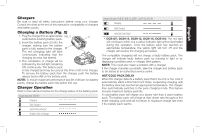
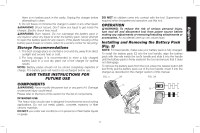
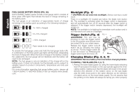
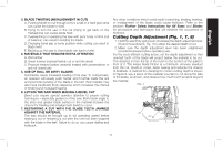
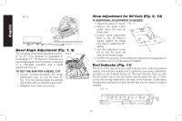
English FUEL GAUGE BATTERY PACKS (FIG. 3A) Some DeWALT battery packs include a fuel gauge which consists of three green LED lights that indicate the level of charge remaining in the battery pack. The fuel gauge is an indication of approximate levels of charge remaining in the battery pack according to the following indicators: 75-100% charged 51-74% charged < 50% charged Pack needs to be charged To actuate the fuel gauge, press and hold the fuel gauge button (R). A combination of the three green LED lights will illuminate designating the level of charge left. When the level of charge in the battery is below the usable limit, the fuel gauge will not illuminate and the battery will need to be recharged. NOTE: The fuel gauge is only an indication of the charge left on the battery pack. It does not indicate tool functionality and is subject to variation based on product components, temperature and end-user application. For more information regarding fuel gauge battery packs, please call 1-800-4-DeWALT (1-800-433-9258) or visit our website www.dewalt. com. Worklight (Fig. 1) CAUTION: Do not stare into worklight. Serious eye injury could result. There is a worklight (O) located just below the blade lock button (K). The worklight is activated when the trigger switch is depressed, and will automatically turn off 20 seconds after the trigger switch is released. If the trigger switch remains depressed, the worklight will remain on. NOTE: The worklight is for lighting the immediate work surface and is not intended to be used as a flashlight. Trigger Switch (Fig. 4) FIG. 4 A WARNING: This tool has no B provision to lock the trigger switch in the ON position and should never be locked ON by any other means. Release the trigger switch lock-off button (A) by pressing the button as shown. Pull the trigger switch (B) to turn the motor on. Releasing the trigger switch turns the motor off. Changing Blades (Fig. 5, 6, 7) WARNING: Remove battery from tool before changing blades. TO INSTALL THE BLADE (FIG. 5, 6, 7) 1. Retract the lower blade guard (G) using the lower blade retracting lever (F) and place the blade on the saw spindle against the inner clamp washer, making sure that the blade will rotate in the proper direction (the direction of the rotation arrow on the saw blade and the teeth must point in the same direction as the direction of rotation arrow on the lower blade guard). Do not assume that the printing on the blade will always be facing you when properly 12
-
 1
1 -
2
-
3
-
4
-
5
-
6
-
7
-
8
-
 9
9 -
 10
10 -
 11
11 -
 12
12 -
 13
13 -
 14
14 -
 15
15 -
 16
16 -
 17
17 -
 18
18 -
 19
19 -
20
-
21
-
22
-
23
-
24
-
25
-
26
-
27
-
28
-
29
-
30
-
31
-
32
-
33
-
34
-
35
-
36
-
37
-
38
-
39
-
40
-
41
-
42
-
43
-
44
-
45
-
46
-
47
-
48
-
49
-
50
-
51
-
52
-
53
-
54
-
55
-
56
-
57
-
58
-
59
-
60
-
61
-
62
-
63
-
64
-
65
-
66
-
67
-
68
-
69
-
70
-
71
-
72
-
73
-
74
-
75
-
76
 |
 |
