Dewalt DWE4011 Instruction Manual - Page 10
ASSEMBLY AND ADJUSTMENTS, Rotating the Gear Case, Fig. 3
 |
View all Dewalt DWE4011 manuals
Add to My Manuals
Save this manual to your list of manuals |
Page 10 highlights
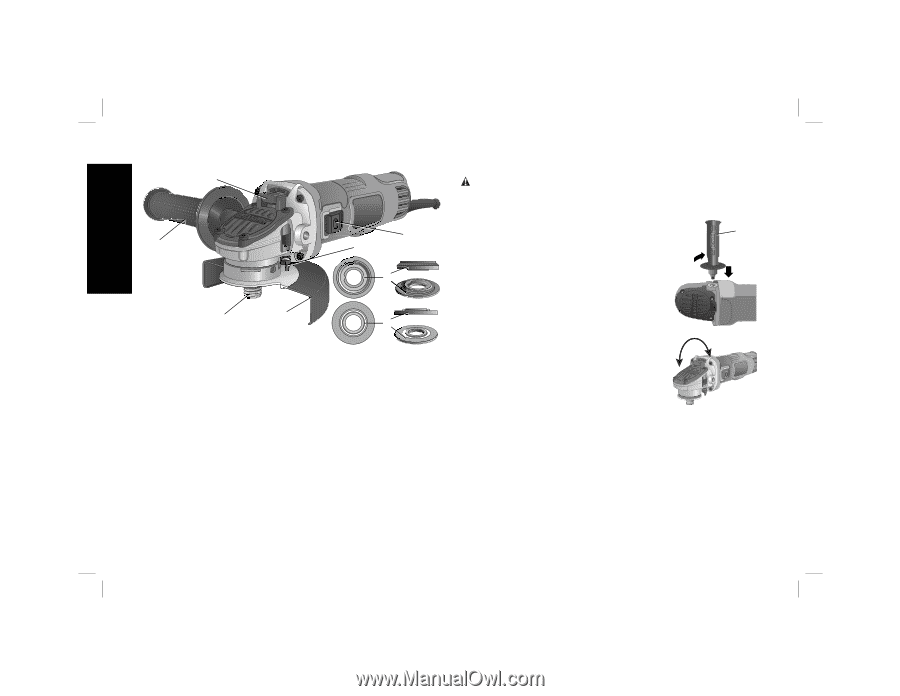
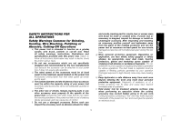
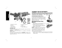
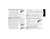
English FIG. 1 A G C H D B F E A. Spindle lock button B. Spindle C. Side handle D. Backing flange E. Threaded clamp nut F. Guard G. Slider switch H. Guard release lever INTENDED USE This grinder is designed for professional grinder, sander, wire brush, polisher or cut-off applications. DO NOT use under wet conditions or in presence of flammable liquids or gases. This grinder is a professional power tool. DO NOT let children come into contact with the tool. Supervision is required when inexperienced operators use this tool. ASSEMBLY AND ADJUSTMENTS WARNING: To reduce the risk of injury, turn unit off and disconnect it from power source before installing and removing accessories, before adjusting or when making repairs. An accidental start-up can cause injury. ATTACHING SIDE HANDLE (FIG. 2) FIG. 2 C The side handle (C) can be fitted to either side of the gear case in the threaded holes, as shown. Before using the tool, check that the handle is tightened securely. Use a wrench to firmly tighten the side handle. Rotating the Gear Case (Fig. 3) 1. Removethefourcornerscrewsattaching FIG. 3 the gear case to motor housing. 2. Without separating the gear case from motor housing, rotate the gear case head to desired position. NOTE: If the gear case and motor housing become separated by more than 1/8" 90˚ 90˚ (3.17 mm), the tool must be serviced and re-assembled by a DEWALT service center. Failure to have the tool serviced may cause brush, motor and bearing failure. 3. Reinstall screws to attach the gear case to the motor housing. Tighten screws to 18 in.-lbs. torque. Overtightening could cause screws to strip. 8
-
 1
1 -
2
-
3
-
4
-
 5
5 -
 6
6 -
 7
7 -
 8
8 -
 9
9 -
 10
10 -
 11
11 -
 12
12 -
 13
13 -
 14
14 -
 15
15 -
16
-
17
-
18
-
19
-
20
-
21
-
22
-
23
-
24
-
25
-
26
-
27
-
28
-
29
-
30
-
31
-
32
-
33
-
34
-
35
-
36
-
37
-
38
-
39
-
40
-
41
-
42
-
43
-
44
-
45
-
46
-
47
-
48
-
49
-
50
-
51
-
52
-
53
-
54
-
55
-
56
-
57
-
58
-
59
-
60
-
61
-
62
-
63
 |
 |