Dewalt DWE4011 Instruction Manual - Page 18
MAINTENANCE, Cleaning - replacement parts
 |
View all Dewalt DWE4011 manuals
Add to My Manuals
Save this manual to your list of manuals |
Page 18 highlights
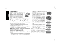
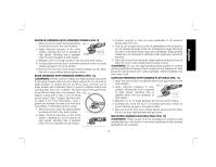
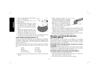
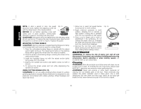
English NOTE: If, after a period of time, the guard FIG. 18 becomes loose, tighten the adjusting screw (O) with the clamp lever in the closed position. O NOTICE: Do not tighten adjusting screw with clamp lever in open position. Undetectable damage to guard or mounting hub may result. CAUTION: If the guard cannot be tightened by the adjusting clamp, do not use the tool. To reduce the risk of personal injury, take the tool and guard to a service center to repair or replace the guard. MOUNTING CUTTING WHEELS CAUTION: Matching diameter threaded backing flange and clamp nut (included with tool) must be used for cutting wheels. 1. Place the unthreaded backing flange on spindle with the raised section (pilot) facing up. The raised section (pilot) on the backing flange will be against the wheel when the wheel is installed. 2. Place the wheel on the backing flange, centering the wheel on the raised section (pilot). 3. Install the threaded clamp nut with the raised section (pilot) facing away from the wheel. 4. Depress the spindle lock button and tighten clamp nut with a wrench. 5. To remove the wheel, grasp and turn while depressing the spindle lock button. USING CUTTING WHEELS (FIG. 19) WARNING: Do not use edge grinding/cutting wheels for surface grinding applications because these wheels are not designed for side pressures encountered with surface grinding. Wheel breakage and injury may result. 1. Allow tool to reach full speed before touching tool to work surface. 2. Apply minimum pressure to work surface, allowing tool to operate at high speed. Cutting rate is greatest when the tool operates at high speed. 3. Once a cut is begun and a notch is established in the workpiece, do not change the angle of the cut. Changing the angle will cause the wheel to bend and may cause wheel breakage. 4. Remove the tool from work surface before turning tool off. Allow the tool to stop rotating before setting it down. FIG. 19 MAINTENANCE WARNING: To reduce the risk of injury, turn unit off and disconnect it from power source before installing and removing accessories, before adjusting or when making repairs. An accidental start-up can cause injury. Cleaning WARNING: Blow dirt and dust out of all air vents with clean, dry air at least once a week. To minimize the risk of eye injury, always wear ANSI Z87.1 approved eye protection when performing this. WARNING: Never use solvents or other harsh chemicals for cleaning the non-metallic parts of the tool. These chemicals may weaken the plastic materials used in these parts. Use a cloth dampened only with water and mild soap. Never let any liquid get inside the tool; never immerse any part of the tool into a liquid. 16
-
 1
1 -
2
-
3
-
4
-
5
-
6
-
7
-
8
-
9
-
10
-
11
-
12
-
 13
13 -
 14
14 -
 15
15 -
 16
16 -
 17
17 -
 18
18 -
 19
19 -
 20
20 -
 21
21 -
 22
22 -
 23
23 -
24
-
25
-
26
-
27
-
28
-
29
-
30
-
31
-
32
-
33
-
34
-
35
-
36
-
37
-
38
-
39
-
40
-
41
-
42
-
43
-
44
-
45
-
46
-
47
-
48
-
49
-
50
-
51
-
52
-
53
-
54
-
55
-
56
-
57
-
58
-
59
-
60
-
61
-
62
-
63
 |
 |
