Dewalt DWE4011 Instruction Manual - Page 12
/2 114.3 mm Cutting Wheels, Sanding Discs, 1/2 114.3 mm Sanding Flap, Discs - case
 |
View all Dewalt DWE4011 manuals
Add to My Manuals
Save this manual to your list of manuals |
Page 12 highlights
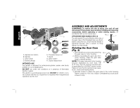
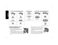
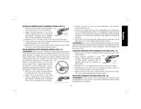
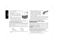
4-1/2" (114.3 mm) Cutting Wheels Sanding Discs 4-1/2" (114.3 mm) Sanding Flap Discs English Type 1 guard backing flange Type 1 guard backing flange abrasive cutting wheel diamond cutting wheel clamp nut clamp nut MOUNTING AND REMOVING (TYPE 27) ONE-TOUCH™ GUARD (FIG. 4, 5) 1. Press the guard release lever (H). 2. While holding the guard release lever open, align the lugs (I) on the guard with the slots on the gear case (J). 3. Keeping the guard release lever open, push the guard down until engage the lugs and rotate them into the groove on the gear case hub. Release the guard release lever. FIG. 4 I J rubber backing pad sanding disc threaded clamp nut Type 27 guard hubbed sanding flap disc Type 27 guard backing flange non-hubbed sanding flap disc threaded clamp nut 4. With the spindle facing the operator, rotate FIG. 5 the guard clockwise into the desired working position. The guard body should K be positioned between the spindle and the operator to provide maximum operator protection. 5. For easy adjustment, the guard can be rotated in the clockwise direction. NOTE: H The guard release lever should snap into one of the alignment holes (K) on the 10
-
 1
1 -
2
-
3
-
4
-
5
-
6
-
 7
7 -
 8
8 -
 9
9 -
 10
10 -
 11
11 -
 12
12 -
 13
13 -
 14
14 -
 15
15 -
 16
16 -
 17
17 -
18
-
19
-
20
-
21
-
22
-
23
-
24
-
25
-
26
-
27
-
28
-
29
-
30
-
31
-
32
-
33
-
34
-
35
-
36
-
37
-
38
-
39
-
40
-
41
-
42
-
43
-
44
-
45
-
46
-
47
-
48
-
49
-
50
-
51
-
52
-
53
-
54
-
55
-
56
-
57
-
58
-
59
-
60
-
61
-
62
-
63
 |
 |
