Dewalt DWE4011 Instruction Manual - Page 17
Mounting and Using Cutting, Type 1 Wheels - discs for angle grinder
 |
View all Dewalt DWE4011 manuals
Add to My Manuals
Save this manual to your list of manuals |
Page 17 highlights
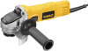
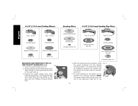
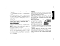
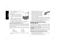
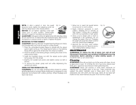
English NOTICE: Failure to properly seat the wheel hub before turning the tool on may result in damage to tool or wheel. USING WIRE CUP BRUSHES AND WIRE WHEELS (FIG 14, 15) Wire wheels and brushes can be used forremoving rust, scale and paint, and for smoothing irregular surfaces. 1. Allow the tool to reach full speed before FIG. 14 touching the tool to the work surface. 2. Apply minimum pressure to work surface, allowing the tool to operate at high speed. Material removal rate is greatest 5˚-10˚ when the tool operates at high speed. 3. Maintain a 5˚ to 10˚ angle between the tool and work surface for wire cup brushes. 4. Maintain contact between the edge of the wheel and the work surface with wire wheels. 5. Continuously move the tool in a forward and FIG. 15 back motion to avoid creating gouges in the work surface. Allowing the tool to rest on the work surface without moving, or moving the tool in a circular motion causes burning and swirling marks on the work surface. 6. Remove the tool from the work surface before turning the tool off. Allow the tool to stop rotating before setting it down. CAUTION: Use extra care when working over an edge, as a sudden sharp movement of grinder may be experienced. Mounting and Using Cutting (Type 1) Wheels Cutting wheels include diamond wheels and abrasive discs. Abrasive cutting wheels for metal and concrete use are available. Diamond blades for concrete cutting can also be used. WARNING: A closed, 2-sided cutting wheel guard is not included with this tool but is required when using cutting wheels. Failure to use proper flange and guard can result in injury resulting from wheel breakage and wheel contact. See page 9 for more information. MOUNTING CLOSED (TYPE 1) GUARD (FIG. 16 -18) NOTE: If present, the One-Touch™ Guard lever, screw, and spring should be removed before attempting to mount the guard. 1. Open the guard latch (N). Align the FIG. 16 lugs (I) on the guard with the slots (J) on the gear case. J 2. Push the guard down until the guard lug engages and rotates freely in the groove on the gear case hub. 3. Rotate guard (F) into desired working position. The guard body should be positioned between the K spindle and the operator to provide N maximum operator protection. 4. Close the guard latch to secure the FIG. 17 guard on the gear case cover. You should be unable to rotate the guard by hand when the latch is in closed position. If rotation is possible, tighten the adjusting screw (O) with clamp lever in the closed position. Do not operate F grinder with a loose guard or clamp lever in open position. 5. To remove the guard, open the guard latch, rotate the guard so that the arrows are aligned and pull up on the guard. 15
-
 1
1 -
2
-
3
-
4
-
5
-
6
-
7
-
8
-
9
-
10
-
11
-
 12
12 -
 13
13 -
 14
14 -
 15
15 -
 16
16 -
 17
17 -
 18
18 -
 19
19 -
 20
20 -
 21
21 -
 22
22 -
23
-
24
-
25
-
26
-
27
-
28
-
29
-
30
-
31
-
32
-
33
-
34
-
35
-
36
-
37
-
38
-
39
-
40
-
41
-
42
-
43
-
44
-
45
-
46
-
47
-
48
-
49
-
50
-
51
-
52
-
53
-
54
-
55
-
56
-
57
-
58
-
59
-
60
-
61
-
62
-
63
 |
 |