Dewalt DWE402N Instruction Manual - Page 11
Accessories, Motor, ASSEMBLY AND ADJUSTMENTS, Attaching Side Handle Fig. 2, Rotating the Gear Case - manual
 |
View all Dewalt DWE402N manuals
Add to My Manuals
Save this manual to your list of manuals |
Page 11 highlights
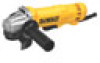
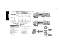
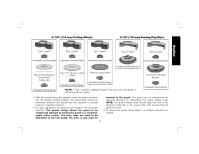
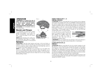
English Motor Be sure your power supply agrees with the nameplate marking. Voltage decrease of more than 10% will cause loss of power and overheating. DEWALT tools are factory tested; if this tool does not operate, check power supply. INTENDED USE These heavy-duty small angle grinders have been designed for professional grinding, sanding, wire brush, and cut-off applications at various work sites (i.e., construction sites). DO NOT use under wet conditions or in presence of flammable liquids or gases. These heavy-duty small angle grinders are professional power tools. DO NOT let children come into contact with the tool. Supervision is required when inexperienced operators use this tool. ASSEMBLY AND ADJUSTMENTS WARNING: To reduce the risk of injury, turn unit off and disconnect it from power source before making any adjustments or removing/installing attachments or accessories. An accidental start-up can cause injury. Attaching Side Handle (Fig. 2) The side handle (F) can be fitted to either side of the gear case in the threaded holes. Before using the tool, check that the handle is tightened securely. To improve user comfort, the gear case will rotate 90° for cutting operations. Rotating the Gear Case (Fig. 2) 1. Remove the four corner screws attaching the gear case to motor housing. 2. Without separating the gear case from motor housing, rotate the gear case head to desired position. NOTE: If the gear case and motor housing FIG. 2 become separated by more than 1/8" (3.17 mm), the tool must be serviced and re-assembled by a DEWALT service center. Failure to have the tool serviced may cause brush, motor and bearing failure. 3. Reinstall screws to attach the gear case 90˚ 90˚ to the motor housing. Tighten screws to 20 in.-lbs. torque. Overtightening could cause screws to strip. Accessories The capacity of this tool is 4 1/2" (115 mm) diameter x 1/4" (6.35 mm) thick grinding or cutting wheels. It is important to choose the correct guards, backing pads and flanges to use with grinder accessories. See pages 10 and 11 for information on choosing the correct accessories. WARNING: Accessories must be rated for at least the speed recommended on the tool warning label. Wheels and other accessories running over their rated accessory speed may fly apart and cause injury. Threaded accessories must have a 5/8"-11 hub. Every unthreaded accessory must have a 7/8" (22.2 mm) arbor hole. If it does not, it may have been designed for a circular saw. Use only the accessories shown on pages 10 and 11 of this manual. Accessory ratings must always be above tool speed as shown on tool nameplate. WARNING: Handle and store all abrasive wheels carefully to prevent damage from thermal shock, heat, mechanical damage, etc. Store in a dry protected area free from high humidity, freezing temperatures or extreme temperature changes. 9
-
 1
1 -
2
-
3
-
4
-
5
-
 6
6 -
 7
7 -
 8
8 -
 9
9 -
 10
10 -
 11
11 -
 12
12 -
 13
13 -
 14
14 -
 15
15 -
 16
16 -
17
-
18
-
19
-
20
-
21
-
22
-
23
-
24
-
25
-
26
-
27
-
28
-
29
-
30
-
31
-
32
-
33
-
34
-
35
-
36
-
37
-
38
-
39
-
40
-
41
-
42
-
43
-
44
-
45
-
46
-
47
-
48
-
49
-
50
-
51
-
52
-
53
-
54
-
55
-
56
-
57
-
58
-
59
-
60
-
61
-
62
-
63
-
64
-
65
-
66
-
67
-
68
-
69
-
70
-
71
-
72
 |
 |