Dewalt DWE402N Instruction Manual - Page 20
Mounting and Using Type 1/Type 41, Cutting Wheels
 |
View all Dewalt DWE402N manuals
Add to My Manuals
Save this manual to your list of manuals |
Page 20 highlights
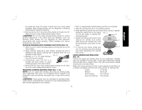
English 5. Continuously move the tool in a forward and back motion to avoid creating gouges in the work surface. Allowing the tool to rest on the work surface without moving, or moving the tool in a circular motion causes burning and swirling marks on the work surface. 6. Remove the tool from the work surface before turning the tool off. Allow the tool to stop rotating before setting it down. CAUTION: Use extra care when working over an edge, as a sudden sharp movement of grinder may be experienced. Mounting and Using Type 1/Type 41 Cutting Wheels NOTE: The Type 1 guard MUST be used and is available at extra cost from your local dealer or authorized service center. Cutting wheels include diamond wheels and abrasive discs. Abrasive cutting wheels for metal and concrete use are available. Diamond blades for concrete cutting can also be used. WARNING: A closed, two-sided cutting wheel guard is required when using cutting wheels. Failure to use proper flange and guard can result in injury resulting from wheel breakage and wheel contact. See pages 10 and 11 for more information. MOUNTING AND REMOVING (TYPE 1) ONE-TOUCH™ GUARD (FIG. 18) Cutting wheels include diamond wheels and abrasive discs. Abrasive cutting wheels for metal and concrete use are available. Diamond blades for concrete cutting can also be used. MOUNTING CLOSED (TYPE 1) GUARD CAUTION: Turn off and unplug the tool before making any adjustments or removing or installing attachments or accessories. Before reconnecting the tool, depress and release the paddle switch to ensure that the tool is off. Your grinder is supplied with a keyless ONE TOUCH™ guard. 1. Press the guard release lever (J). 2. While holding the guard release lever open, align the lugs (L) on the guard with the slots (M) on the gear case. 3. Keeping the guard release lever FIG. 18 L open, push the guard down until the guard lugs engage and rotate them in the groove on the gear case hub. Release the guard release lever. 4. With the spindle facing the operator, rotate the guard clockwise into the desired working position. The M N M guard body should be positioned between the spindle and the operator to provide maximum operator protection. 5. For easy adjustment, the guard can be rotated in the clockwise J direction. NOTE: The guard release lever should snap into one of the alignment holes (O) on the guard collar. This insures that the guard is secure. The guard can be repositioned the opposite direction by depressing the guard release lever. 6. To remove the guard, follow steps 1-3 of these instructions in reverse. 18
-
 1
1 -
2
-
3
-
4
-
5
-
6
-
7
-
8
-
9
-
10
-
11
-
12
-
13
-
14
-
 15
15 -
 16
16 -
 17
17 -
 18
18 -
 19
19 -
 20
20 -
 21
21 -
 22
22 -
 23
23 -
 24
24 -
 25
25 -
26
-
27
-
28
-
29
-
30
-
31
-
32
-
33
-
34
-
35
-
36
-
37
-
38
-
39
-
40
-
41
-
42
-
43
-
44
-
45
-
46
-
47
-
48
-
49
-
50
-
51
-
52
-
53
-
54
-
55
-
56
-
57
-
58
-
59
-
60
-
61
-
62
-
63
-
64
-
65
-
66
-
67
-
68
-
69
-
70
-
71
-
72
 |
 |