Dewalt DWE402N Instruction Manual - Page 15
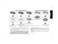
Mounting and Using Depressed Center, Grinding Wheels, Sanding Flap Discs and, Hubbed Wheels
 |
View all Dewalt DWE402N manuals
Add to My Manuals
Save this manual to your list of manuals |
Page 15 highlights
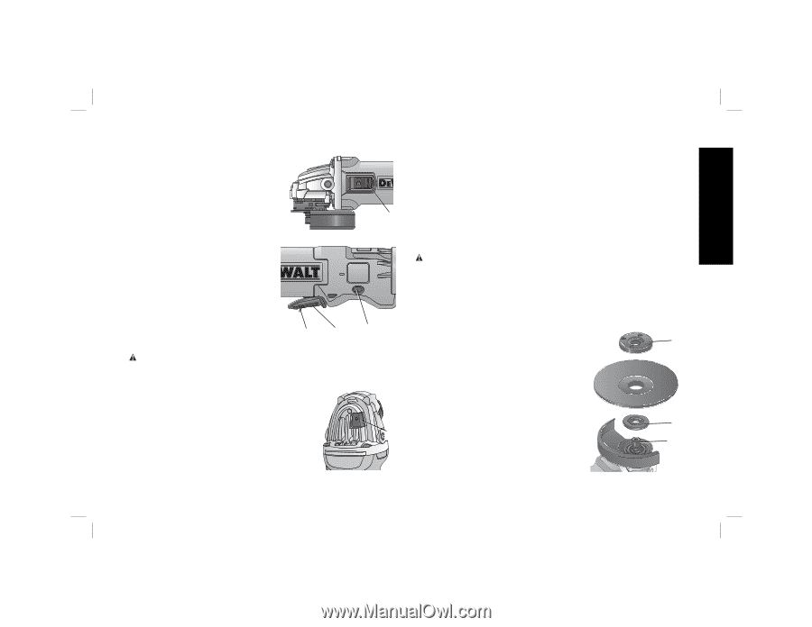
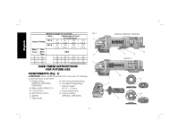
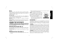
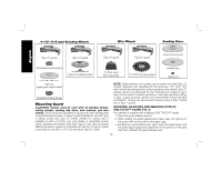
English For continuous operation, slide the switch (B) toward the front of the tool and press the forward part of the switch inward. To stop the tool while operating in continuous mode, press the rear part of the switch and release. FIG. 5 LOCK-ON BUTTON (FIG. 6) B DWE402, DWE402G The lock-on button (K) offers FIG. 6 increased comfort in extended use applications. To lock the tool on, push the lock-off lever (C) toward the back of the tool then depress the paddle switch (A). With the tool running, depress the lock-on button (K). The tool will continue to run after the paddle switch is released. To unlock the tool, depress and release the paddle switch. This C A K will cause the tool to stop. CAUTION: Allow the tool to reach full speed before touching tool to the work surface. Lift the tool from the work surface before turning the tool off. SPINDLE LOCK BUTTON (FIG. 7) FIG. 7 The spindle lock button (D) is provided to prevent the spindle from rotating when installing or removing wheels. Operate the spindle lock button only when the tool is D turned off, the tool is unplugged, and the wheel has come to a complete stop. NOTICE: To reduce the risk of damage to the tool, do not engage the spindle lock button while the tool is operating. Damage to the tool will result and attached accessory may spin off possibly resulting in injury. To engage the lock, depress the spindle lock button (D) and rotate the spindle until you are unable to rotate the spindle further. Mounting and Using Depressed Center Grinding Wheels, Sanding Flap Discs and Hubbed Wheels CAUTION: Always use the correct guard per the instructions in this manual. MOUNTING NON-HUBBED WHEELS (FIG. 8, 9) Depressed center Type 27 and Type 42 grinding wheels must be used with included flanges. See pages 10 and 11 of this manual for more information. 1. Install the unthreaded backing flange FIG. 8 (G) on spindle (E) with the raised section (pilot) against the wheel. Be H sure the backing flange recess is seated onto the flats of the spindle by pushing and twisting the flange before placing wheel. 2. Place wheel against the backing flange, centering the wheel on the raised section (pilot) of the backing flange. G E 13
-
 1
1 -
2
-
3
-
4
-
5
-
6
-
7
-
8
-
9
-
 10
10 -
 11
11 -
 12
12 -
 13
13 -
 14
14 -
 15
15 -
 16
16 -
 17
17 -
 18
18 -
 19
19 -
 20
20 -
21
-
22
-
23
-
24
-
25
-
26
-
27
-
28
-
29
-
30
-
31
-
32
-
33
-
34
-
35
-
36
-
37
-
38
-
39
-
40
-
41
-
42
-
43
-
44
-
45
-
46
-
47
-
48
-
49
-
50
-
51
-
52
-
53
-
54
-
55
-
56
-
57
-
58
-
59
-
60
-
61
-
62
-
63
-
64
-
65
-
66
-
67
-
68
-
69
-
70
-
71
-
72
 |
 |