Dewalt DXCMH9919910 Instruction Manual - Page 10
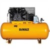
Assembly Fig. 1
 |
View all Dewalt DXCMH9919910 manuals
Add to My Manuals
Save this manual to your list of manuals |
Page 10 highlights
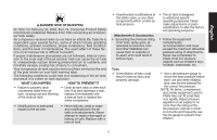
English reaches cut-out pressure, the check valve closes, allowing air pressure to remain inside the air tank. AIR INTAKE FILTER A The filter (A) is designed to clean air entering the pump. To ensure the pump continually receives a clean, cool, and dry air supply the filter must always be clean and the filter intake must be free from obstructions. AIR TANK DRAIN VALVE The drain valve (F) is located at the base of the air tank and is used to drain condensation at the end of each use. See Draining Air Tank under Maintenance. F TANK PRESSURE GAUGE The tank pressure gauge (C) indicates the J reserve air pressure in the tank. C MAGNETIC STARTER NOTE: These units require a magnetic starter. Magnetic starters (J) that are not factory mounted on the compressor can be mounted on the wall if desired. Mount as close to compressor as possible. Size the wires, protect them with conduit, and provide branch circuit protection per the National Electrical Code. GLOBE VALVE/AIR DISCHARGE VALVE: (sold separately, not shown) Opens and closes air distribution from compressor. See Air Distribution System paragraph under Installation. REGULATOR (sold separately, not shown): An air pressure regulator or a separate air transformer which combines the functions of air regulation and/or moisture and dirt removal is recommended for most applications. See Air Distribution System paragraph under Installation. AIR COMPRESSOR PUMP The pump compresses air into the air tank. Working air is not available until the compressor has raised the air tank pressure above that required at the air outlet. MAGNETIC STARTER RESET SWITCH If the motor shuts down because of overload, wait 10-15 minutes so the motor can cool down. To restart: 1. Set the Auto/Off switch to OFF (O). K 2. Allow the motor to cool. 3. Depress the reset button (K) on the magnetic starter. 4. Set the Auto/Off switch to AUTO (-). INSTALLATION Assembly (Fig. 1) Unpack the air compressor. Inspect the unit for damage. If the unit has been damaged in transit, contact the carrier and complete a damage claim. Do this immediately because there are time limitations to damage claims. The carton should contain: • air compressor • operator and parts manuals Check the compressor's serial label to ensure that you have received the model ordered, and that it has the required pressure 10
-
 1
1 -
2
-
3
-
4
-
 5
5 -
 6
6 -
 7
7 -
 8
8 -
 9
9 -
 10
10 -
 11
11 -
 12
12 -
 13
13 -
 14
14 -
 15
15 -
16
-
17
-
18
-
19
-
20
-
21
-
22
-
23
-
24
-
25
-
26
-
27
-
28
-
29
-
30
-
31
-
32
-
33
-
34
-
35
-
36
-
37
-
38
-
39
-
40
-
41
-
42
-
43
-
44
-
45
-
46
-
47
-
48
-
49
-
50
-
51
-
52
-
53
-
54
-
55
-
56
-
57
-
58
-
59
-
60
-
61
-
62
-
63
-
64
-
65
-
66
-
67
-
68
-
69
-
70
-
71
-
72
-
73
-
74
-
75
-
76
-
77
-
78
-
79
-
80
-
81
-
82
-
83
-
84
-
85
-
86
-
87
-
88
-
89
-
90
-
91
-
92
 |
 |
