E-Z-GO TXT - Gas Owner Manual - Page 30
Air Intake And Cooling Fins
 |
View all E-Z-GO TXT - Gas manuals
Add to My Manuals
Save this manual to your list of manuals |
Page 30 highlights
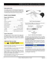
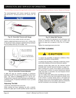
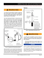
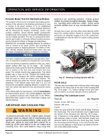
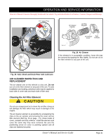
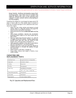
OPERATION AND SERVICE INFORMATION Read all of Manual to become thoroughly familiar with this vehicle. Pay particular attention to all Notices, Cautions, Dangers and Warnings Periodic Brake Test For Mechanical Brakes The purpose of this test is to compare the braking performance of the vehicle to the braking performance of new or 'known to be good' vehicles or to an established acceptable stopping distance. Actual stopping distances will be influenced by weather conditions, terrain, road surface condition, actual vehicle weight (accessories installed) and vehicle speed. No specific braking distance can be reliably specified. The test is conducted by latching the park brake to eliminate different pedal pressures and to include the affects of linkage mis-adjustment. Establish the acceptable stopping distance by testing a new or 'known to be good' vehicle and recording the stopping location or stopping distance. For fleets of vehicles, several vehicles should be tested when new and the range of stopping locations or distances recorded. NOTICE Over time, a subtle loss of performance may take place; therefore, it is important to establish the standard with a new vehicle. Drive the vehicle at maximum speed on a flat, dry, clean, paved surface (Ref Fig. 26 on page - 19). Quickly depress the brake pedal to latch the parking brake at the line or marker in the test area and remove foot from pedal. The vehicle should stop aggressively. The wheel brakes may or may not lock. Observe the vehicle stopping location or measure the vehicle stopping distance from the point at which the brakes were latched. The vehicle should stop within the 'normal' range of stopping distances. If the vehicle stops more than 4 ft. (1.2 m) beyond the acceptable stopping distance or pulls to one side, the vehicle has failed the test and should be tested again. If the vehicle fails the second test, it should immediately be removed from service. The vehicle must be inspected by a qualified mechanic who should refer to the TROUBLESHOOTING section in the Technician's Repair and Service Manual. AIR INTAKE AND COOLING FINS To prevent possible burns, engine parts should be kept clean to reduce risk of overheating and ignition of accumulated debris. After every off road use, allow to cool and then check for a build up of dirt and debris in the air intake and cooling fins. Dirt and debris may clog the engine's air cooling system. Clean areas shown to prevent engine damage. Keep linkages, springs and controls clean. Keep area around muffler free of any combustible material. At least once a year, (or more often under adverse conditions) the cooling system should be cleaned. Cleaning will assure an adequate supply of air to the cooling fins. Compressed air may be used for routine cooling system maintenance. Fig. 27 Cleaning Cooling System with Air REAR AXLE The rear axle is provided with a lubricant level check plug located on the driver side at the rear of the housing (Ref Fig. 28 on page - 21). Unless leakage of rear axle lubricant is evident, an annual lubricant check is sufficient. Checking The Lubricant Level Tool List Qty. Required Socket, 13 mm, 3/8" drive 1 Ratchet, 3/8" drive 1 Funnel 1 Clean the area around the check and fill plugs. Remove the check plug. The correct lubricant level is just below the bottom of the threaded hole (Ref Fig. 28 on page 21). If lubricant is to be added, remove the fill plug and add lubricant using a funnel. Add lubricant slowly until lubricant starts to seep from the check plug hole. Install the check plug and the fill plug. In the event that the lubricant is to be replaced, a drain plug is provided at the bottom of the differential housing. Page 20 Owner's Manual and Service Guide
-
 1
1 -
2
-
3
-
4
-
5
-
6
-
7
-
8
-
9
-
10
-
11
-
12
-
13
-
14
-
15
-
16
-
17
-
18
-
19
-
20
-
21
-
22
-
23
-
24
-
 25
25 -
 26
26 -
 27
27 -
 28
28 -
 29
29 -
 30
30 -
 31
31 -
 32
32 -
 33
33 -
 34
34 -
 35
35 -
36
-
37
-
38
-
39
-
40
-
41
-
42
-
43
-
44
-
45
-
46
-
47
-
48
-
49
-
50
-
51
-
52
-
53
-
54
-
55
-
56
-
57
-
58
 |
 |