Electrolux EFME617STT Installation Instructions English Spanish French - Page 14
Gas connection
 |
View all Electrolux EFME617STT manuals
Add to My Manuals
Save this manual to your list of manuals |
Page 14 highlights
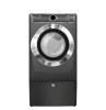
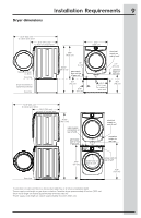
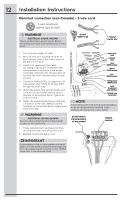
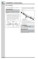
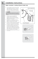
14 Installation Instructions Gas connection 1. Remove the shipping cap from gas pipe at the rear of the dryer. IMPORTANT DO NOT connect the dryer to L.P. gas service without converting the gas valve. An L.P. conversion kit must be installed by a qualified gas technician. 3. Open the shutoff valve in the gas supply line to allow gas to flow through the pipe. Wait a few minutes for gas to move through the gas line. to dryer 2. Connect a 1/2 inch (1.27 cm) I.D. semi-rigid or approved pipe from gas supply line to the 3/8 inch (0.96 cm) pipe located on the back of the dryer. Use a 1/2 inch to 3/8 inch (1.27 cm to 0.96 cm) reducer for the connection. Apply an approved thread sealer that is resistant to the corrosive action of liquefied gases on all pipe connections. Shutoff Valve Open position from gas supply Manual Shutoff Flare Valve Union GAS FLOW Flare Union Closed Nipple Open Flexible Connector Inlet Pipe on Back of Dryer All connections must be wrench-tightened 4. Check for gas system leaks with a manometer. If a manometer is not available, test all connections by brushing on a soapy water solution. WARNING EXPLOSION HAZARD NEVER test for gas leaks with an open flame. IMPORTANT Installation to the gas service must follow local codes and ordinances and the latest edition of the National Fuel Gas Code ANSI Z223.1/NEPA 54 or in Canada, CSA B149.1.
-
 1
1 -
2
-
3
-
4
-
5
-
6
-
7
-
8
-
 9
9 -
 10
10 -
 11
11 -
 12
12 -
 13
13 -
 14
14 -
 15
15 -
 16
16 -
 17
17 -
 18
18 -
 19
19 -
20
-
21
-
22
-
23
-
24
-
25
-
26
-
27
-
28
-
29
-
30
-
31
-
32
-
33
-
34
-
35
-
36
-
37
-
38
-
39
-
40
-
41
-
42
-
43
-
44
-
45
-
46
-
47
-
48
-
49
-
50
-
51
-
52
-
53
-
54
-
55
-
56
-
57
-
58
-
59
-
60
-
61
-
62
-
63
-
64
 |
 |