Epson FX-100 User Manual - Page 159
FX-100, Enters Single-Density Graphics Mode and spe
 |
View all Epson FX-100 manuals
Add to My Manuals
Save this manual to your list of manuals |
Page 159 highlights
Summary You enter Graphics Mode with the CHR$(27)"K" cCoHluRm$ (nns1)bCyHfRill$in( ng2 ) command. You determine the number of the two reservation slots, n1, and n2. You graphics fire your pin patterns by adding up the pin labels, which consist of powers of two. Here is the command we introduced in this chapter: CHR$(27)"K"CHRS(n 1,)CHR$(n2); Enters Single-Density Graphics Mode and specifies width setting. Width = n1+256*n 2 where n1 is 0 - 255 and n2 is 0 - 7 on the FX-80 and 0 - 12 on the FX-100 Note: Single-Density graphics dots are printed 60 per inch horizontally and 72 per inch vertically. 142
-
 1
1 -
2
-
3
-
4
-
5
-
6
-
7
-
8
-
9
-
10
-
11
-
12
-
13
-
14
-
15
-
16
-
17
-
18
-
19
-
20
-
21
-
22
-
23
-
24
-
25
-
26
-
27
-
28
-
29
-
30
-
31
-
32
-
33
-
34
-
35
-
36
-
37
-
38
-
39
-
40
-
41
-
42
-
43
-
44
-
45
-
46
-
47
-
48
-
49
-
50
-
51
-
52
-
53
-
54
-
55
-
56
-
57
-
58
-
59
-
60
-
61
-
62
-
63
-
64
-
65
-
66
-
67
-
68
-
69
-
70
-
71
-
72
-
73
-
74
-
75
-
76
-
77
-
78
-
79
-
80
-
81
-
82
-
83
-
84
-
85
-
86
-
87
-
88
-
89
-
90
-
91
-
92
-
93
-
94
-
95
-
96
-
97
-
98
-
99
-
100
-
101
-
102
-
103
-
104
-
105
-
106
-
107
-
108
-
109
-
110
-
111
-
112
-
113
-
114
-
115
-
116
-
117
-
118
-
119
-
120
-
121
-
122
-
123
-
124
-
125
-
126
-
127
-
128
-
129
-
130
-
131
-
132
-
133
-
134
-
135
-
136
-
137
-
138
-
139
-
140
-
141
-
142
-
143
-
144
-
145
-
146
-
147
-
148
-
149
-
150
-
151
-
152
-
153
-
 154
154 -
 155
155 -
 156
156 -
 157
157 -
 158
158 -
 159
159 -
 160
160 -
 161
161 -
 162
162 -
 163
163 -
 164
164 -
165
-
166
-
167
-
168
-
169
-
170
-
171
-
172
-
173
-
174
-
175
-
176
-
177
-
178
-
179
-
180
-
181
-
182
-
183
-
184
-
185
-
186
-
187
-
188
-
189
-
190
-
191
-
192
-
193
-
194
-
195
-
196
-
197
-
198
-
199
-
200
-
201
-
202
-
203
-
204
-
205
-
206
-
207
-
208
-
209
-
210
-
211
-
212
-
213
-
214
-
215
-
216
-
217
-
218
-
219
-
220
-
221
-
222
-
223
-
224
-
225
-
226
-
227
-
228
-
229
-
230
-
231
-
232
-
233
-
234
-
235
-
236
-
237
-
238
-
239
-
240
-
241
-
242
-
243
-
244
-
245
-
246
-
247
-
248
-
249
-
250
-
251
-
252
-
253
-
254
-
255
-
256
-
257
-
258
-
259
-
260
-
261
-
262
-
263
-
264
-
265
-
266
-
267
-
268
 |
 |

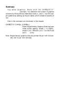
Summary
You enter Graphics
Mode with the CHR$(27)“K”
CHR$(n
1
)CHR$(n
2
)
command. You determine the number of graphics
columns by filling the two reservation slots, n
1
, and n
2
. You fire your
pin patterns by adding up the pin labels, which consist of powers of
two.
Here is the command we introduced in this chapter:
CHR$(27)“K”CHRS(n
1
,)CHR$(n
2
);
Enters Single-Density Graphics Mode and spe-
cifies width setting. Width = n
1
+256*n
2
where n
1
is 0 - 255 and n
2
is 0 - 7 on the FX-80
and 0 -
12
on the
FX-100
Note: Single-Density graphics dots are printed 60 per inch horizon-
tally and 72 per inch vertically.
142