Epson PowerLite 530 Projector for SMART Installation Guide - Short-Throw Wall - Page 25
Route the cables through the arm unit, 4. Attach the wall mount to the wall plate
 |
View all Epson PowerLite 530 Projector for SMART manuals
Add to My Manuals
Save this manual to your list of manuals |
Page 25 highlights
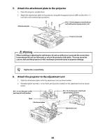
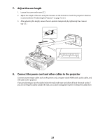
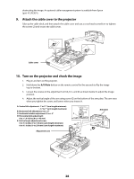
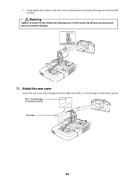
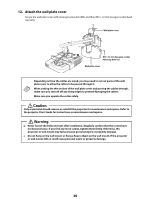
3. Route the cables through the arm unit Route the projector's power cord and any additional cables connecting to the projector through the arm unit. q Be sure to also route the cables for any optional equipment (for example document camera, speakers, etc.) that may be used in the future. Otherwise, each time you need to connect another device, you will need to remove the projector from the mount to connect additional cables. Arm unit Vertical adjustment screw Caution Problems may occur if you use this product without routing the cables through the arm unit. q Route the USB cable so that the type B connector emerges on the projector side. Epson recommends labeling any duplicate cables so that additional connections can be more easily identified. 4. Attach the wall mount to the wall plate 1. Attach the hook on the arm plate to the bar on the wall plate. 2. Partially tighten two M8 × 16 mm hexagon socket head cap bolts to secure the arm plate . Bar on wall plate Arm plate Wall plate Arm unit M8 × 16 mm hexagon socket head cap bolt (×2) Caution Take care not to trap the cables between the mount arm and wall plate. 25
-
 1
1 -
2
-
3
-
4
-
5
-
6
-
7
-
8
-
9
-
10
-
11
-
12
-
13
-
14
-
15
-
16
-
17
-
18
-
19
-
 20
20 -
 21
21 -
 22
22 -
 23
23 -
 24
24 -
 25
25 -
 26
26 -
 27
27 -
 28
28 -
 29
29 -
 30
30 -
31
-
32
-
33
-
34
-
35
-
36
-
37
-
38
-
39
-
40
-
41
-
42
-
43
-
44
-
45
-
46
-
47
-
48
-
49
-
50
-
51
-
52
-
53
-
54
-
55
-
56
-
57
-
58
-
59
-
60
-
61
-
62
-
63
-
64
 |
 |
