Epson PowerLite 530 Projector for SMART Installation Guide - Short-Throw Wall - Page 28
Attach the cable cover to the projector, 10. Turn on the projector and check the image, A/V Mute
 |
View all Epson PowerLite 530 Projector for SMART manuals
Add to My Manuals
Save this manual to your list of manuals |
Page 28 highlights
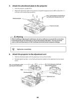
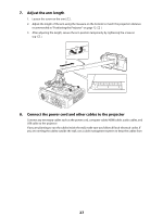
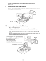
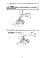
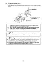
obstructing the image. An optional cable management system is available from Epson (part # ELPCK01). 9. Attach the cable cover to the projector Take up the cable slack, and then attach the cable cover and use a cross-head screwdriver to tighten the screws (2) and secure the cable cover. Cable cover 10. Turn on the projector and check the image 1. Plug in and turn on the projector. 2. Hold down the A/V Mute button on the remote control for five seconds to flip the image top-to-bottom. 3. Loosen the screws on the adjustment unit (A, B, C, and D) as shown below to adjust the image position. 4. Adjust the vertical angle of the arm using screw (E) on the bottom of the arm plate. The arm rises when you tighten the screw, and lowers when you loosen it. A: Vertical tilt adjustment: -7 to 17° (arm length minimum) : -17 to 7° (arm length maximum) B: Horizontal roll adjustment: 0 to ± 5° C: Horizontal rotation adjustment: 0 to ± 5° D: Horizontal slide adjustment: 0 to ± 1.8 inches (0 to ± 45 mm) E: Vertical angle adjustment screw: 0 to 5.3 inches (0 to 134 mm) (arm length minimum) 0 to 9.1 inches (0 to 230 mm) (arm length maximum) Arm plate Adjustment unit 28
-
 1
1 -
2
-
3
-
4
-
5
-
6
-
7
-
8
-
9
-
10
-
11
-
12
-
13
-
14
-
15
-
16
-
17
-
18
-
19
-
20
-
21
-
22
-
 23
23 -
 24
24 -
 25
25 -
 26
26 -
 27
27 -
 28
28 -
 29
29 -
 30
30 -
 31
31 -
 32
32 -
 33
33 -
34
-
35
-
36
-
37
-
38
-
39
-
40
-
41
-
42
-
43
-
44
-
45
-
46
-
47
-
48
-
49
-
50
-
51
-
52
-
53
-
54
-
55
-
56
-
57
-
58
-
59
-
60
-
61
-
62
-
63
-
64
 |
 |
