Epson SureColor F6070 User Manual - Page 10
See Loading Roll Paper on See Control Panel - chip
 |
View all Epson SureColor F6070 manuals
Add to My Manuals
Save this manual to your list of manuals |
Page 10 highlights
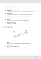
4 Ink tanks Hold ink used for printing. 5 Slider (chip holder) See "Slider (chip holder)" on page 11. 6 Side cover Open the side cover to remove the slider for chip unit replacement. Always close the side cover securely after inserting the slider. 7 AC inlet Connect the supplied power cable here. 8 Option port No options are currently available for the printer. 9 LAN port Connects the LAN cable. 10 Data light The network connection status and data reception are indicated by a lit or flashing light. On : Connected. Flashing : Receiving data. 11 Status light The color indicates the network transmission speed. Off : 10Base-T Red : 100Base-T Green : 1000Base-T 12 USB port Connect the USB cable here. 13 Control panel See "Control Panel" on page 13. 14 Alert lamp This lamp lights or flashes when an error occurs. Lights or : An error has occurred. How the lamp lights or flashes varies with the type of error. flashes The control panel displays a description of the error. Off : No error. 15 Roll rest When loading roll paper, place it on this rest and attach the roll paper adapters. See "Loading Roll Paper" on page 27. Introduction 10
-
 1
1 -
2
-
3
-
4
-
 5
5 -
 6
6 -
 7
7 -
 8
8 -
 9
9 -
 10
10 -
 11
11 -
 12
12 -
 13
13 -
 14
14 -
 15
15 -
16
-
17
-
18
-
19
-
20
-
21
-
22
-
23
-
24
-
25
-
26
-
27
-
28
-
29
-
30
-
31
-
32
-
33
-
34
-
35
-
36
-
37
-
38
-
39
-
40
-
41
-
42
-
43
-
44
-
45
-
46
-
47
-
48
-
49
-
50
-
51
-
52
-
53
-
54
-
55
-
56
-
57
-
58
-
59
-
60
-
61
-
62
-
63
-
64
-
65
-
66
-
67
-
68
-
69
-
70
-
71
-
72
-
73
-
74
-
75
-
76
-
77
-
78
-
79
-
80
-
81
-
82
-
83
-
84
-
85
-
86
-
87
-
88
-
89
-
90
-
91
-
92
-
93
-
94
-
95
-
96
-
97
-
98
-
99
-
100
-
101
-
102
-
103
-
104
-
105
-
106
-
107
-
108
-
109
-
110
-
111
 |
 |
