Fluke 1773/BASIC Product Manual - Page 11
GPS Time Synchronization, WiFi Antenna Connection
 |
View all Fluke 1773/BASIC manuals
Add to My Manuals
Save this manual to your list of manuals |
Page 11 highlights
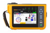
1773/1775/1777 Users Manual An adapter cable (available from Fluke) connects the antenna to the installed WiFi/BLE module. See Figure 2. Figure 2. WiFi Antenna Connection PN 5263915 Note The antenna cable connects to the antenna with a SMA connector that has an outside thread and a center receptacle (SMA female/jack). Former FCC regulations required that WiFi equipment must use reverse polarity connectors. You must use an SMA male plug to RP-SMA female adapter if the antenna uses a RP-SMA male connector with an internal thread and center receptacle. XW Warning To prevent possible electrical shock, fire, or personal injury, use Productapproved measurement category (CAT) antenna cables when the Product is installed in environment where wires or exposed metal parts provide access to hazardous live voltage, such as, in cabinets. GPS Time Synchronization With a GPS antenna, the Analyzer has the best possible real-time accuracy of typically 1 ms and complies to the time synchronization requirements of IEC61000-4-30 Class A. To use GPS time synchronization: 1. Go to Instrument Setup > Time Synchronization Source and configure as GPS. The GPS status on the Analyzer indicates an invalid time synchronization status and no connection to the GPS receiver. 2. Attach the antenna cable to the GPS Input Connector. See Figure 3. 6 MyFlukeStore Shop for Fluke products online at: www. .com 1.888.610.7664
-
 1
1 -
2
-
3
-
4
-
5
-
 6
6 -
 7
7 -
 8
8 -
 9
9 -
 10
10 -
 11
11 -
 12
12 -
 13
13 -
 14
14 -
 15
15 -
 16
16 -
17
-
18
-
19
-
20
-
21
-
22
-
23
-
24
-
25
-
26
-
27
-
28
-
29
-
30
-
31
-
32
-
33
-
34
-
35
-
36
-
37
-
38
-
39
-
40
-
41
-
42
-
43
-
44
-
45
-
46
-
47
-
48
-
49
-
50
-
51
-
52
-
53
-
54
-
55
-
56
-
57
-
58
-
59
-
60
-
61
 |
 |
