Fluke 1773/BASIC Product Manual - Page 44
Communication Settings, Phase Power Quality Analyzer, Ethernet., WiFi client., WiFi Access Point.
 |
View all Fluke 1773/BASIC manuals
Add to My Manuals
Save this manual to your list of manuals |
Page 44 highlights
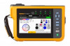
3 Phase Power Quality Analyzer Basic Setup Communication Settings These setting relate to communications with the Anaylzer. Ethernet. The instrument address can be set automatically or manually. The default setting is Automatic when you select Ethernet from the settings list. For Manual setting, deselect Ethernet and set the inputs for IP Address, Netmask, Gateway, and DNS. Note Only change these settings if you have the required networking knowledge. A check box allows you to turn off the option for all wireless interfaces when required in sensitive locations. WiFi client. This setting directly connects the Anaylzer to the local WiFi network and allows access to the Anaylzer from any location within the WiFi network. When the WiFi client is off, the available network access points appear in a list in screen. The network password is required to connect to the local network. Select the network and enter the password with the on-screen keyboard. It is not possible to enter a username and password. WiFi Access Point. The Anaylzer can be set as a WiFi Access point and creates its own WiFi network that a device can connect to. This can be used to download data from the Anaylzer with Fluke Energy Analyze software or for control with a Virtual Network Computer. See Remote Display. The WiFi direct connection uses WPA2-PSK (pre-shared key) with AES encryption. The passphrase shown on the screen is required to establish a connection from a client to the device. To setup: 1. On the client, go to the list of available WiFi networks and look for the network name: Fluke177x For example: Fluke1777 2. At the prompt, enter the passphrase provided on the WiFi Configuration screen. Depending on the operating system of the client, the passphrase is also called Security Key, Password, or similar. After a few seconds the connection is established. Note On the PC, the WiFi icon in the notification area of the task bar shows (the icon varies for the Windows version). The icon indicates that this WiFi interface does not provide an Internet access. This is normal since the Analyzer is not a gateway to the Internet. 39 MyFlukeStore Shop for Fluke products online at: www. .com 1.888.610.7664
-
 1
1 -
2
-
3
-
4
-
5
-
6
-
7
-
8
-
9
-
10
-
11
-
12
-
13
-
14
-
15
-
16
-
17
-
18
-
19
-
20
-
21
-
22
-
23
-
24
-
25
-
26
-
27
-
28
-
29
-
30
-
31
-
32
-
33
-
34
-
35
-
36
-
37
-
38
-
 39
39 -
 40
40 -
 41
41 -
 42
42 -
 43
43 -
 44
44 -
 45
45 -
 46
46 -
 47
47 -
 48
48 -
 49
49 -
50
-
51
-
52
-
53
-
54
-
55
-
56
-
57
-
58
-
59
-
60
-
61
 |
 |
