Fluke 725Ex FE 725ex Users Manual - Page 29
Using Measure Mode, Measuring Electrical Parameters (Upper Display)
 |
View all Fluke 725Ex manuals
Add to My Manuals
Save this manual to your list of manuals |
Page 29 highlights
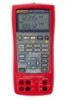
Using Measure Mode Measuring Electrical Parameters (Upper Display) To measure the current or voltage output of a transmitter, or to measure the output of a pressure instrument, use the upper display and proceed as follows: 1. Press l to select volts or current. LOOP should not be on. 2. Connect the leads as shown in Figure 7. Current Measurement with Loop Power The loop power function activates a 12-V supply in series with the current measuring circuit, allowing the user to test a transmitter when it is disconnected from plant wiring. To measure current with loop power, proceed as follows: 1. Connect the Calibrator to the transmitter current loop terminals as shown in Figure 8. 2. Press l while the Calibrator is in current measurement mode. LOOP appears and an internal 12-V loop supply turns on. Using Measure Mode 725Ex MULTIFUNCTION PROCESS CALIBRATOR V mA LOOP ZERO MEAS SOURCE STORE SETUP V mA TC RTD 2004.1573266 LR110460 Zone 0 AEx ia IIB 171 C I.S. Class I Div 1, Groups B,C,D RECALL Hz ˚C ˚F 100% 25% 25% 0% Red Black aly42f.eps Figure 7. Measuring Voltage and Current Output 19
-
 1
1 -
2
-
3
-
4
-
5
-
6
-
7
-
8
-
9
-
10
-
11
-
12
-
13
-
14
-
15
-
16
-
17
-
18
-
19
-
20
-
21
-
22
-
23
-
 24
24 -
 25
25 -
 26
26 -
 27
27 -
 28
28 -
 29
29 -
 30
30 -
 31
31 -
 32
32 -
 33
33 -
 34
34 -
35
-
36
-
37
-
38
-
39
-
40
-
41
-
42
-
43
-
44
-
45
-
46
-
47
-
48
-
49
-
50
-
51
-
52
-
53
-
54
-
55
-
56
-
57
-
58
-
59
-
60
-
61
-
62
-
63
-
64
-
65
-
66
-
67
-
68
-
69
-
70
 |
 |
