Fluke 87V Getting Started Guide - Page 27
Table 15. Electrical Characteristics of the Terminals, Table 16. MIN MAX Recording Specifications - input impedance
 |
View all Fluke 87V manuals
Add to My Manuals
Save this manual to your list of manuals |
Page 27 highlights
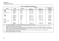
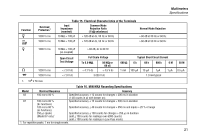
Multimeters Specifications Function L FmV Overload Protection1 1000 V rms 1000 V rms Table 15. Electrical Characteristics of the Terminals Input Impedance (nominal) Common Mode Rejection Ratio (1 kΩ unbalance) Normal Mode Rejection 10 MΩ < 100 pF > 120 dB at dc, 50 Hz or 60 Hz > 60 dB at 50 Hz or 60 Hz 10 MΩ < 100 pF > 120 dB at dc, 50 Hz or 60 Hz > 60 dB at 50 Hz or 60 Hz K 1000 V rms 10 MΩ < 100 pF > 60 dB, dc to 60 Hz (ac-coupled) Open Circuit Test Voltage Full Scale Voltage To 6.0 MΩ 50 MΩ or 60 nS 600 Ω Typical Short Circuit Current 6 k 60 k 600 k 6 M e 1000 V rms < 7.9 V dc < 4.1 V dc < 4.5 V dc 1 mA 100 μA 10 μA 1μA 1 μA G 1000 V rms < 7.9 V dc 3.000 V dc 1.0 mA typical 1. 106 V Hz max Table 16. MIN MAX Recording Specifications Model Nominal Response Accuracy 83 100 ms to 80 % Specified accuracy ± 12 counts for changes > 200 ms in duration (± 40 counts in ac with beeper on) 87 100 ms to 80 % (dc functions) Specified accuracy ± 12 counts for changes > 200 ms in duration 120 ms to 80 % (ac functions) 250 μs (peak) (Model 87 only)1 Specified accuracy ± 40 counts for changes > 350 ms and inputs > 25 % of range Specified accuracy ± 100 counts for changes > 250 μs in duration (add ± 100 counts for readings over 6000 counts) (add ± 100 counts for readings in Low Pass mode) 1. For repetitive peaks: 1 ms for single events. 50 M 0.5 μA 21
-
 1
1 -
2
-
3
-
4
-
5
-
6
-
7
-
8
-
9
-
10
-
11
-
12
-
13
-
14
-
15
-
16
-
17
-
18
-
19
-
20
-
21
-
 22
22 -
 23
23 -
 24
24 -
 25
25 -
 26
26 -
 27
27 -
 28
28
 |
 |
