Fluke N4K 2PP42I Product Manual - Page 23
Operating Controls and Display, Display, Table 3-2. Display Descriptions, Description
 |
View all Fluke N4K 2PP42I manuals
Add to My Manuals
Save this manual to your list of manuals |
Page 23 highlights
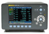
NORMA 4000/5000 Operators Manual Operating Controls and Display The display, operating controls, and function keys are located at the front of the Power Analyzer. The display consists of a menu bar, a section in which the measured values and the channel settings are shown, and the assignment bar for the function keys. Figure 3-2 illustrates the location of the operating controls on the display and Table 3-2 is a list of control descriptions. 12 3 4 5 13 NORMA 5000 POWER ANALYZER 6 ESC ENTER 12 11 10 7 HOLD RUN MEM 1...n WAV 9 8 Figure 3-2. Display esn006.eps Item 1 2 3 4 5 6 7 8 9 10 11 12 13 Table 3-2. Display Descriptions Description Display of configuration; menu item General Setup Menu item Integration Setup/Motor-Generator Setup Measurement status/display of average time Display of synchronization source frequency; menu item Timing & Sync Setup Display of time; menu item Clock Setup Navigation keys Measuring keys Display for measured values Function keys Assignment bar for function keys Information row Status display for channels 1 to 6 (including measuring range, coupling, and modulation bar); menu items Current Channel Setup and Voltage Channel Setup Menu bar with menu items 3-4 MyFlukeStore Shop for Fluke products online at: www. .com 1.888.610.7664
-
 1
1 -
2
-
3
-
4
-
5
-
6
-
7
-
8
-
9
-
10
-
11
-
12
-
13
-
14
-
15
-
16
-
17
-
 18
18 -
 19
19 -
 20
20 -
 21
21 -
 22
22 -
 23
23 -
 24
24 -
 25
25 -
 26
26 -
 27
27 -
 28
28 -
29
-
30
-
31
-
32
-
33
-
34
-
35
-
36
-
37
-
38
-
39
-
40
-
41
-
42
-
43
-
44
-
45
-
46
-
47
-
48
-
49
-
50
-
51
-
52
-
53
-
54
-
55
-
56
-
57
-
58
-
59
-
60
-
61
-
62
-
63
-
64
-
65
-
66
-
67
-
68
-
69
-
70
-
71
-
72
-
73
-
74
-
75
-
76
-
77
-
78
-
79
-
80
-
81
-
82
-
83
-
84
-
85
-
86
-
87
-
88
-
89
-
90
-
91
-
92
-
93
-
94
-
95
-
96
-
97
-
98
-
99
-
100
-
101
-
102
-
103
-
104
-
105
-
106
-
107
-
108
-
109
-
110
-
111
-
112
-
113
-
114
-
115
-
116
-
117
-
118
-
119
-
120
-
121
-
122
-
123
-
124
-
125
-
126
-
127
-
128
-
129
-
130
-
131
-
132
-
133
-
134
-
135
-
136
-
137
-
138
-
139
-
140
-
141
-
142
-
143
-
144
-
145
 |
 |
