Foxconn A7DA-S 3.0 English Manual. - Page 21
Fan Connectors : CPU_FAN, SYS_FAN, NB_FAN, Speaker Connector : SPEAKER, COM Connector : COM1
 |
View all Foxconn A7DA-S 3.0 manuals
Add to My Manuals
Save this manual to your list of manuals |
Page 21 highlights
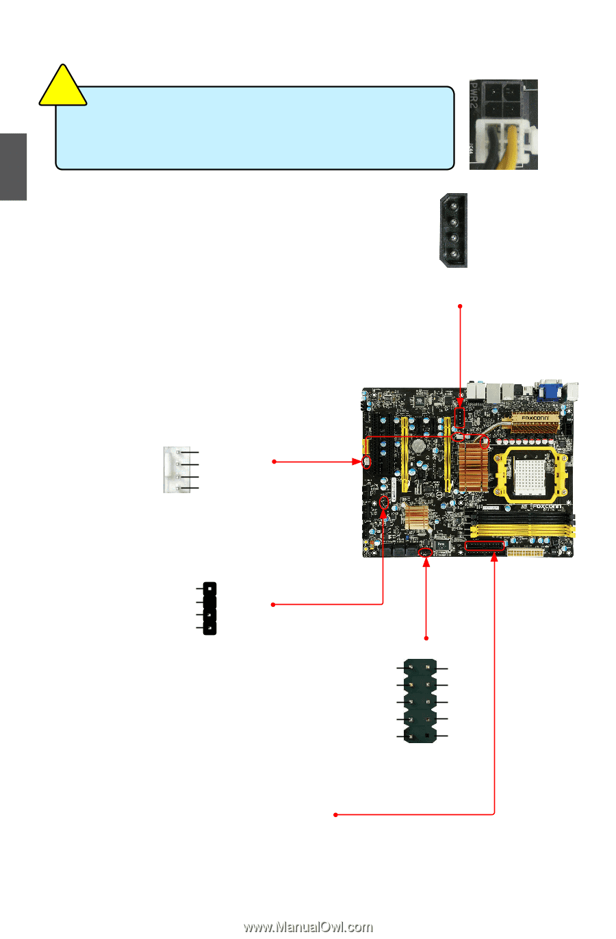
2 CAUTION ! We recommend you using an 8-pin ATX 12V power supply. If you are using a 4-pin power supply, you need to align the ATX power connector according to the picture on the right. Connect a 4-pin power plug Exclusive Graphics power Connector : PWR3 This connector is an auxiliary power for graphics card. Exclusive power for graphics card is for better graphics performance and future upgrade usage. Fan Connectors : CPU_FAN, SYS_FAN, NB_FAN There are three main fan headers on this motherboard. The fan speed can be controlled and monitored in "PC Health Status" section of the BIOS Setup. These fans can be automatically turned off after the system enters S3, S4 and S5 sleeping states. 1 GND POWER SENSE CONTROL CPU_FAN/SYS_FAN/NB_FAN Speaker Connector : SPEAKER The speaker connector is used to connect speaker of the chassis. SPKJ 1 EMPTY 2 NC 3 SPKJ 4 SPEAKER COM Connector : COM1 This motherboard supports one serial RS232 COM port for legacy compatibility. User must purchase another RS232 cable with a 9-pin D-sub connector at one end to connect with the external RS232 device and another end with 10-pin female connector to connect with COM1 connector in the motherboard. 1 +12V GND GND +5V 4 PWR3 12 RLSD SIN SOUT DTR GND DSR RTS CTS RI EMPTY 9 10 COM1 Floppy Disk Drive Connector : FLOPPY This motherboard includes a standard floppy disk drive (FDD) connector, supporting 360KB, 720KB, 1.2MB, 1.44MB, and 2.88MB FDDs. 14
-
 1
1 -
2
-
3
-
4
-
5
-
6
-
7
-
8
-
9
-
10
-
11
-
12
-
13
-
14
-
15
-
 16
16 -
 17
17 -
 18
18 -
 19
19 -
 20
20 -
 21
21 -
 22
22 -
 23
23 -
 24
24 -
 25
25 -
 26
26 -
27
-
28
-
29
-
30
-
31
-
32
-
33
-
34
-
35
-
36
-
37
-
38
-
39
-
40
-
41
-
42
-
43
-
44
-
45
-
46
-
47
-
48
-
49
-
50
-
51
-
52
-
53
-
54
-
55
-
56
-
57
-
58
-
59
-
60
-
61
-
62
-
63
-
64
-
65
-
66
-
67
-
68
-
69
-
70
-
71
-
72
-
73
-
74
-
75
-
76
-
77
-
78
-
79
-
80
-
81
-
82
-
83
-
84
-
85
-
86
-
87
-
88
-
89
-
90
-
91
-
92
-
93
-
94
-
95
-
96
-
97
-
98
-
99
-
100
-
101
-
102
-
103
-
104
-
105
-
106
-
107
-
108
-
109
-
110
-
111
-
112
 |
 |