Foxconn A7DA-S 3.0 English Manual. - Page 44
► Power Down Enable, ► Power Down Mode, ► DCT Unganged Mode
 |
View all Foxconn A7DA-S 3.0 manuals
Add to My Manuals
Save this manual to your list of manuals |
Page 44 highlights
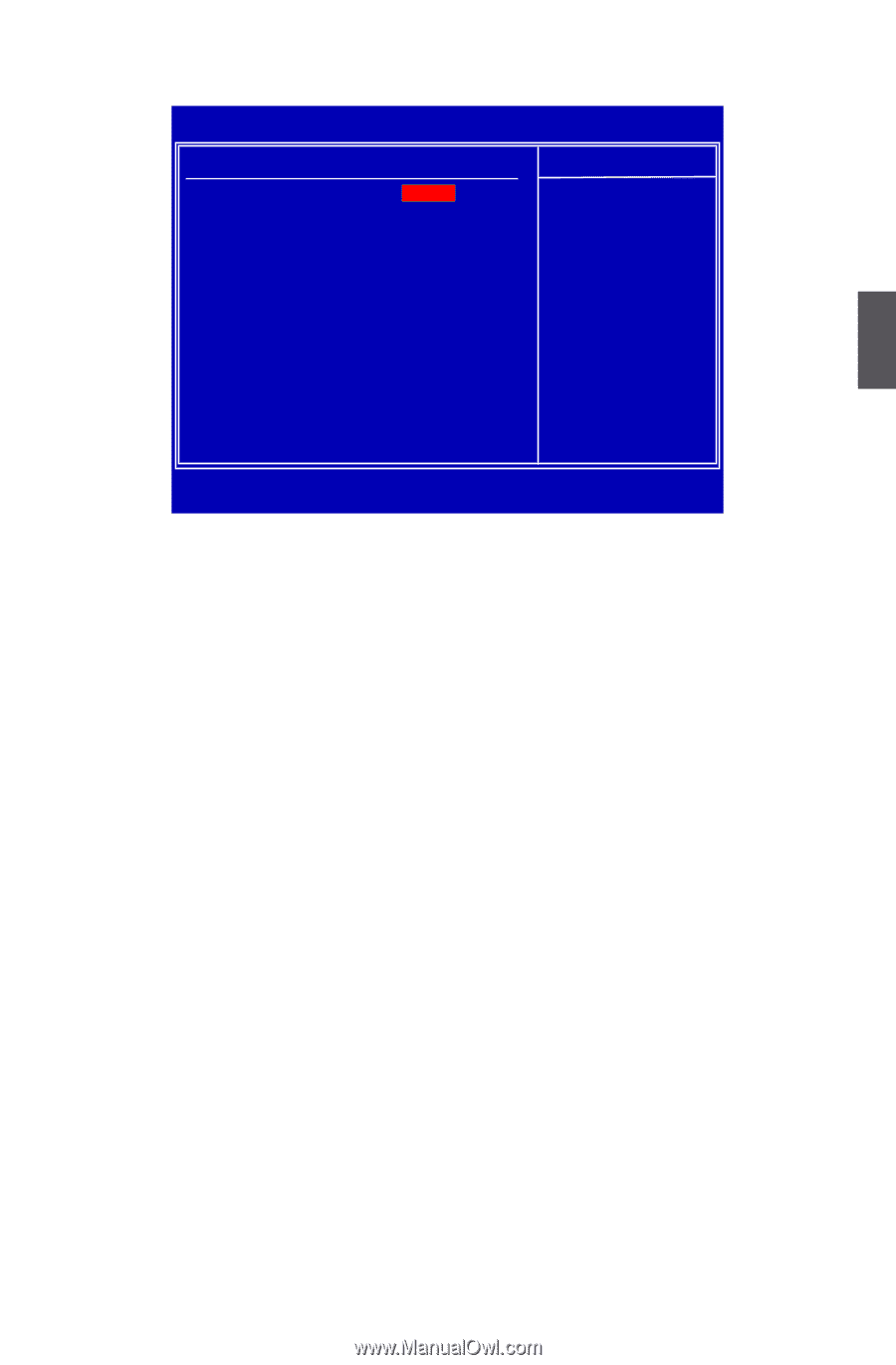
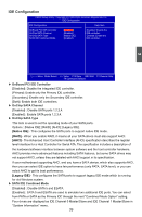
Memory Configuration CMOS Setup Utility - Copyright (C) 1985-2006, American Megatrends, Inc. Memory Configuration Memory Configuration Help Item DCT Unganged Mode [ Always ] Enable memory Power Down Enable [Enabled] remapping around Power Down Mode [Channel] memory hole 3 Move Enter:Select +/-/:Value F10:Save ESC:Exit F1:General Help F9:Optimized Defaults ► DCT Unganged Mode DCT stands for DRAM Controller. Ganged refers to the use of both DRAM controllers within a memory controller acting in concert to access memory. For a description of ganged (128-bit DRAM data width) and unganged (64-bit DRAM data width) DRAM modes : Ganged channels (DDR2) : ■ DCT channels A and B can be ganged as a single logical 128-bit DIMM. ■ Offers highest DDR2 bandwidth. ■ Requires both DIMMs in a logical pair to have identical size and timing parameters, both DCTs programmed identically. Unganged channels ■ DCT channels A and B operate as two completely independent 64-bit channels (both channels operate at the same frequency). ■ Reduce DRAM page conflicts - more concurrent open dram pages . ■ Better bus efficiency. Burst lengths supported When both DCTs are enabled in unganged mode, BIOS must initialize the frequency of each DCT in order. ► Power Down Enable When power down mode is enabled, if all pages of the DRAMs associated with a CKE pin are closed, then these parts are placed in power down mode. ► Power Down Mode For non-mobile systems, power down mode should be set to [Channel] CKE control. A DIMM or a group of DIMMs enters power down mode by deasserting the corresponding clock enable signal when the DRAM controller detects that there are no transactions scheduled to any of the DIMMs connected to the clock enable signal. A DIMM or a group of DIMMs exits power down mode by asserting the corresponding clock enable signal when a transaction is scheduled to any DIMM connected to the clock enable signal. There are two 37
-
 1
1 -
2
-
3
-
4
-
5
-
6
-
7
-
8
-
9
-
10
-
11
-
12
-
13
-
14
-
15
-
16
-
17
-
18
-
19
-
20
-
21
-
22
-
23
-
24
-
25
-
26
-
27
-
28
-
29
-
30
-
31
-
32
-
33
-
34
-
35
-
36
-
37
-
38
-
 39
39 -
 40
40 -
 41
41 -
 42
42 -
 43
43 -
 44
44 -
 45
45 -
 46
46 -
 47
47 -
 48
48 -
 49
49 -
50
-
51
-
52
-
53
-
54
-
55
-
56
-
57
-
58
-
59
-
60
-
61
-
62
-
63
-
64
-
65
-
66
-
67
-
68
-
69
-
70
-
71
-
72
-
73
-
74
-
75
-
76
-
77
-
78
-
79
-
80
-
81
-
82
-
83
-
84
-
85
-
86
-
87
-
88
-
89
-
90
-
91
-
92
-
93
-
94
-
95
-
96
-
97
-
98
-
99
-
100
-
101
-
102
-
103
-
104
-
105
-
106
-
107
-
108
-
109
-
110
-
111
-
112
 |
 |