Foxconn P43AL-V English Manual. - Page 39
► Memory Speed Adjust, ► Memory Timing by SPD, ► PEG Port, ► SMBUS Controller, ► SLP_S4# Min.
 |
View all Foxconn P43AL-V manuals
Add to My Manuals
Save this manual to your list of manuals |
Page 39 highlights
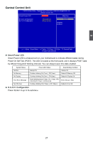
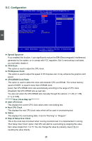
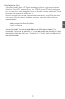
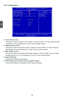
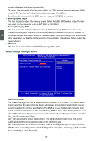
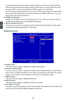
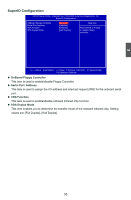
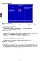
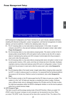
3 sociate addresses with those storage cells. Of course, that only works if you're using a 64-bit (or 32bit physical address extension (PAE) enabled) OS that can deal with physical addresses larger than 32 bits. Once this option is enabled, the BIOS can see maximum 8192 MB of memory. ► Memory Speed Adjust This item is used to adjust the memory speed. Select [Auto] for SPD enable mode. You also can select a value manually such as [667 MHz] or [800 MHz]. ► Memory Timing by SPD This item is used to enable/disable provision of DRAM timing by SPD device. The Serial Presence Detect (SPD) device is a small EEPROM chip, mounted on a memory module. It contains important information about the module's speed, size, addressing mode and various other parameters, so that the motherboard memory controller (chipset) can better access the memory device. ► PEG Port This item is used to enable/disable PCI Express graphics port. South Bridge Configuration CMOS Setup Utility - Copyright (C) 1985-2006, American Megatrends, Inc. South Bridge Configuration South Bridge Chipset Configuration Help Item SMBUS Controller [Enabled] Options SLP_S4# Min. Assertion Width [1 to 2 seconds] Enabled Disabled Move Enter:Select +/-/:Value F10:Save ESC:Exit F1:General Help F9:Optimized Defaults ► SMBUS Controller The System Management Bus is a specific implementation of an I2C bus. The SMBus specification describes the data protocols, device addresses, and electrical requirements that are superimposed on the I2C bus specification. The SMBus is used to physically transport commands and information between the Smart Battery, SMBus Host, Smart Battery Charger, and other SMBus Devices. This item is used to enable/disable System Mangement Bus controller. ► SLP_S4# Min. Assertion Width SLP_S4# is a signal for power plane control. This signal shuts off power to all non-critical systems when in the S4 (Suspend to Disk) or S5 (Soft Off) state. This setting indicates the minimum assertion width of the SLP_S4# signal to ensure that the DRAMs have been safely power-cycled. Setting values are: [4 to 5 seconds], [3 to 4 seconds], [2 to 3 seconds], [1 to 2 seconds]. 32
-
 1
1 -
2
-
3
-
4
-
5
-
6
-
7
-
8
-
9
-
10
-
11
-
12
-
13
-
14
-
15
-
16
-
17
-
18
-
19
-
20
-
21
-
22
-
23
-
24
-
25
-
26
-
27
-
28
-
29
-
30
-
31
-
32
-
33
-
 34
34 -
 35
35 -
 36
36 -
 37
37 -
 38
38 -
 39
39 -
 40
40 -
 41
41 -
 42
42 -
 43
43 -
 44
44 -
45
-
46
-
47
-
48
-
49
-
50
-
51
-
52
-
53
-
54
-
55
-
56
-
57
-
58
-
59
-
60
-
61
-
62
-
63
-
64
-
65
-
66
-
67
-
68
-
69
-
70
-
71
-
72
-
73
-
74
 |
 |
