Frigidaire FGGS3065PF Installation Instructions - Page 14
Fasten Bracket
 |
View all Frigidaire FGGS3065PF manuals
Add to My Manuals
Save this manual to your list of manuals |
Page 14 highlights
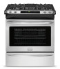
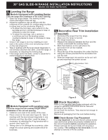
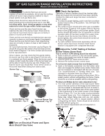
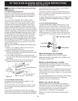
30" GAS SLIDE-IN RANGE INSTALLATION INSTRUCTIONS (Models with Sealed Top Burners) 12.2 Models Equipped with Leveling Legs To reduce the risk of tipping of the range, the range must be secured to the floor by the properly installed anti-tip bracket and screws packed with the range. Failure to install the anti-tip bracket will allow the range to tip over if excessive weight is placed on an open door or if child climbs upon it. Serious injury might result from spilled hot liquids or from the range itself. C. Level and position the range - Slide range to its final position. Insert the range leveling leg in the anti-tip bracket. Visually verify if the anti-tip bracket is engaged. Lower the range by adjusting the 4 leveling legs alternatively until the range is level. Check if the range is level by placing a spirit level on the oven rack. Take 2 readings with the spirit level placed diagonally; take a reading in one direction and then in the other direction. Level the range if necessary by adjusting the leveling legs. If range is ever moved to a different location, the antitip bracket must also be moved and installed with the range. Instructions are provided for installation in wood or cement floor. When fastening to floor, be sure that screws do not penetrate electrical wiring, gas line or plumbing. A. Locate the Bracket Using the Template - Locate the bracket position (right or left side) by placing the template symmetrically to the center of the final range position. Mark the location of the screw holes, shown on template. Range side Figure 22 Figure 20 B. Drill Pilot Holes and Fasten Bracket - Drill a 1/8" (0,3 cm) pilot hole where screws are to be located. If bracket is to be mounted to the wall, drill pilot hole at an approximate 20° downward angle. If bracket is to be mounted to masonry or ceramic floors, drill a 3/16" (0,5 cm) pilot hole 1-3/4" (4,4 cm) deep. The screws provided may be used in wood or concrete material. Use a 5/16" (0,8 cm) nut-driver or flat head screwdriver to secure the bracket in place. FASTEN BRACKET (WALL OR FLOOR MOUNTING) Leveling leg Wall mount Rear of Range Wall Plate Floor Mount Anti-Tip Bracket Figure 21 14 Leg Leveler Raise Lower Figure 23 Figure 24
-
 1
1 -
2
-
3
-
4
-
5
-
6
-
7
-
8
-
 9
9 -
 10
10 -
 11
11 -
 12
12 -
 13
13 -
 14
14 -
 15
15 -
 16
16 -
 17
17 -
 18
18 -
 19
19 -
20
-
21
-
22
-
23
-
24
-
25
-
26
-
27
-
28
-
29
-
30
-
31
-
32
-
33
-
34
-
35
-
36
-
37
-
38
-
39
-
40
-
41
-
42
-
43
-
44
 |
 |
