Frigidaire FGGS3065PF Installation Instructions - Page 6
Before Starting
 |
View all Frigidaire FGGS3065PF manuals
Add to My Manuals
Save this manual to your list of manuals |
Page 6 highlights
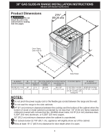
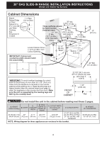
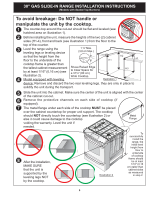
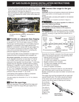
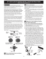
30" GAS SLIDE-IN RANGE INSTALLATION INSTRUCTIONS (Models with Sealed Top Burners) Before Starting Tools you will need For leveling legs and anti-tip brackets: ● Adjustable wrench or channel lock pliers ● 5/16" Nutdriver or Flat Head Screw Driver ● Electric Drill & 1/8 Diameter Drill Bit (5/32" Masonry Drill Bit if installing in concrete) ● Level & Measuring Tape For gas supply connection: ● Pipe Wrench ● Brush For burner flame adjustment: ● Phillips head and blade-type screwdrivers For gas conversion (LP/Propane or Natural): ● Open end wrench - 1/2" Additional materials you will need: ● Gas line shut-off valve ● Pipe joint sealant that resists action of LP/Propane gas ● A new flexible metal appliance conduit (½" NPT x ¾" or ½" I.D.) must be design certified by CSA International. Because solid pipe restricts moving the range we recommend using a new flexible conduit (4 feet length) for each new installation and additional reinstallations. ● Always use the (2) new flare union adapters ½" NPT x ¾" or ½" I.D.) supplied with the new flexible appliance conduit for connection of the range. Min. Cutout Width Formed or tile countertop trimmed ¾" (1,9 cm) back at front corners of countertop opening. Figure 1 • If the existing cutout width is greater than 30-1/16" (76,4 cm), reduce the ¾" (1,9 cm) dimension. • Countertop must be level. Place a level on the countertop, first side to side, then front to back. If the countertop is not level, the range will not be level. The oven must be level for satisfactory baking results. Cooktop sides of range fit over edges of countertop opening. 1.3 Gas and Electric Entry Preparation • The hatched areas are the locations where the gas line can enter the cabinet (figure 2). • The recommended position for the gas entry line is located at 7" (17,8 cm) from the left cabinet wall and 2" (5,1 cm) from the floor (figure 2). • The shaded area is the location where the electric outlet can be located (figure 2). (7360.2) 1. Cabinet Construction 1.1 To eliminate the risk of cabinet burns and fire, do not have cabinet storage space above the range. If there is cabinet storage space above range, reduce risk by installing a range hood that projects horizontally a minimum of 5" (12,7 cm) beyond the bottom of the cabinet. 1.2 Countertop Preparation (figure 1) • The cooktop sides of the range fit over the cutout edge of your countertop. • If you have a square finish (flat) countertop, no countertop preparation is required. Cooktop sides lay directly on edge of countertop. • Formed front-edged countertops must have molded edge shaved flat 3/4" (1,9 cm) from each front corner of opening (Figure 1). • Tile countertops may need trim cut back 3/4"(1,9 cm) from each front corner and/or rounded edge flattened (Figure 1). WALL 2 (5.1) 2 (5.1) 7½ 4.5 5 6 3 12 3 (30.5) 4 2½ 2½ 11 5 Recommended position Note: All dimensions are in inches (centimeter). Figure 2 WALL 6
-
 1
1 -
 2
2 -
 3
3 -
 4
4 -
 5
5 -
 6
6 -
 7
7 -
 8
8 -
 9
9 -
 10
10 -
 11
11 -
 12
12 -
13
-
14
-
15
-
16
-
17
-
18
-
19
-
20
-
21
-
22
-
23
-
24
-
25
-
26
-
27
-
28
-
29
-
30
-
31
-
32
-
33
-
34
-
35
-
36
-
37
-
38
-
39
-
40
-
41
-
42
-
43
-
44
 |
 |
