Frigidaire PLGF659GC Installation Instructions (All Languages) - Page 3
Connect the range to the gas supply, Before Installing the Range, Provide an adequate Gas Supply, - 36 gas range
 |
UPC - 057112098968
View all Frigidaire PLGF659GC manuals
Add to My Manuals
Save this manual to your list of manuals |
Page 3 highlights
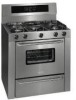
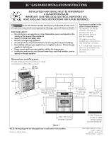
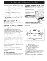
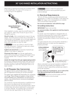
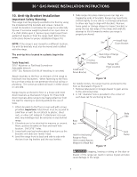
36 " GAS RANGE INSTALLATION INSTRUCTIONS • In the event of an electrical power outage, the surface burners can be lit manually. To light a surface burner, hold a lit match to the burner head and slowly turn the Surface Control knob to LITE. Use caution when lighting surface burners manually. • Reset all controls to the "off" position whenever the oven is done cooking. FOR MODELS WITH SELF-CLEAN FEATURE: • Remove broiler pan, food and other utensils before self-cleaning the oven. Wipe up excess spillage. Follow the precleaning instructions in the Use and Care Guide. • Unlike the standard gas range, THIS COOKTOP IS NOT REMOVABLE. Do not attempt to remove the cooktop. 1. Before Installing the Range Remove shipping material Remove all tape, shipping and packaging materials and the oven rack packaging. 2. Provide an adequate Gas Supply When shipped from the factory, this unit is designed to operate on 4"(10,16 cm) water column (1.0 kPa) Natural gas manifold pressure. A convertible pressure regulator is connected to the range manifold and MUST be connected in series with the gas supply line. If LP/ Propane conversion kit has been used, follow instructions provided with the kit for converting the pressure regulator to LP/Propane use. Care must be taken during installation of range not to obstruct the flow of air for combustion and ventilation. For proper operation, the maximum inlet pressure to the regulator should be no more than 14"(35,56 cm) of water column pressure (3.5 kPa). The inlet pressure to the regulator must be at least 1" (.25 kPa) greater than the regulator manifold pressure setting. Examples: If regulator is set for natural gas 4"(10,16 cm) manifold pressure, inlet pressure must be at least 5"(12.60 cm); if regulator has been converted for LP/Propane gas 10"(25,4 cm) manifold pressure, inlet pressure must be at least 11"(27,9 cm). Leak testing of the appliance shall be conducted according to the instructions in step 4. The gas supply line should be ½" or ¾" I.D. (Interior Diameter) 3. Seal the openings Seal any openings in the wall behind the range and in the floor under the range after gas supply line is installed. 4. Connect the range to the gas supply Important: Remove all packing material and literature from range before connecting gas and electrical supply. To prevent leaks, put pipe joint sealant on all external pipe threads. Your regulator is in location shown below. Do not allow regulator to rotate on pipe when tightening fittings. Pressure Regulator Figure 2 Location Connection to Pressure Regulator The regulator is already installed on the appliance. Do not make the connection too tight. The regulator is die cast. Overtightening may crack the regulator resulting in a gas leak and possible fire or explosion. Manual Shutoff Valve Flare Union GAS FLOW Pressure Flare Regulator Union On Nipple Off Flexible Connector Nipple Access Cap All connections must be wrench-tightened Figure 3 Assemble the flexible connector from the gas supply pipe to the pressure regulator in the following order: 1. manual shutoff valve (not included) 2. 1/2" nipple (not included) 3. 1/2" flare union adapter (not included) 4. flexible connector (not included) 5. 1/2" flare union adapter (not included) 6. 1/2" nipple (not included) 7. pressure regulator (Included) Use pipe-joint compound made for use with Natural and LP/Propane gas to seal all gas connections. If flexible connectors are used, be certain connectors are not kinked. The supply line must be equipped with an approved manual shutoff valve. This valve should be located in the same room as the range and should be in a location that 3
-
 1
1 -
 2
2 -
 3
3 -
 4
4 -
 5
5 -
 6
6 -
 7
7 -
 8
8 -
 9
9 -
10
-
11
-
12
-
13
-
14
-
15
-
16
 |
 |