Frigidaire PLGF659GC Installation Instructions (All Languages) - Page 5
Moving the Appliance for, Servicing and Cleaning, Check Operation - model
 |
UPC - 057112098968
View all Frigidaire PLGF659GC manuals
Add to My Manuals
Save this manual to your list of manuals |
Page 5 highlights
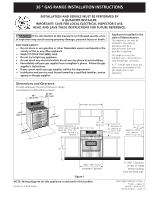
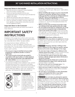
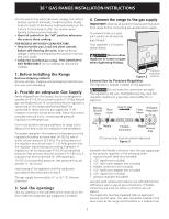
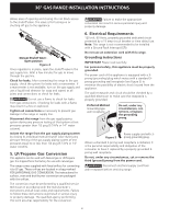
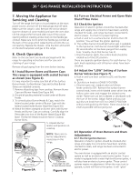
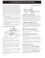
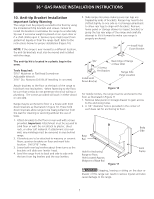
36 " GAS RANGE INSTALLATION INSTRUCTIONS 7. Moving the Appliance for Servicing and Cleaning Turn off the range line fuse or circuit breakers at the main power source, and turn off the manual gas shut-off valve. Make sure the range is cold. Remove the service drawer (warmer drawer on some models) and open the oven door. Lift the range at the front and slide it out of the cut-out opening without creating undue strain on the flexible gas conduit. Make sure not to pinch the flexible gas conduit at the back of the range when replacing the unit into the cutout opening. Replace the drawer, close the door and switch on the electrical power and gas to the range. 8. Check Operation Refer to the Use and Care Guide packaged with the range for operating instructions and for care and cleaning of your range. Remove all packaging from the oven before testing. 8.2 Turn on Electrical Power and Open Main Shutoff Gas Valve 8.3 Check the Igniters Operation of electric igniters should be checked after range and supply line connectors have been carefully checked for leaks, and range has been connected to electric power. To check for proper lighting: a.Push in and turn a surface burner knob to the LITE position. You will hear the igniter sparking. b. The surface burner should light when gas is available to the top burner. Each burner should light within four (4) seconds after air has been purged from supply lines. Visually check that burner has lit. c. Once the burner lights, the control knob should be rotated out of the LITE position. There are separate ignition devices for each burner. Try each knob separately until all burner valves have been checked. 8.1 Install Burner Bases and Burner Caps This range is equipped with sealed burners as shown (see Figure 6). It is very important to make sure that all of the Surface Burner Heads, Surface Burner Caps and Surface Burner Grates are installed correctly. 1. Remove all packing tape from cooktop. Remove Burner Caps and Burner Heads (See Figure 6A). 2. Discard all packing material located under all Burner Heads. 3. To correctly place Burner Heads & Caps, match the letters located under center of Burner Caps with the letters located inside Burner Head (See Figure 6A). 4. Match the letters stamped on Burner skirts with Burner Heads and Burner Caps on cooktop. Carefully align the Electrodes into slots of the Burner Heads (Figure 6B). Note: The Burner Heads should sit flat on Cooktop Burner Skirts. 5. Unpack Burner Grates and position on cooktop. NOTE: There are no burner adjustments necessary on this range. 8.4 Adjust the "LOW" Setting of Surface Burner Valves (see Figure 7) a.Push in and turn each control to LITE until burner ignites. b. Quickly turn knob to LOWEST POSITION. c. If burner goes out, readjust valve as follows: Reset control to OFF. Remove the surface burner control knob, insert a thin-bladed screw driver into the hollow valve stem and engage the slotted screw inside. Flame size can be increased or decreased with the turn of the screw. Adjust flame until you can quickly turn knob from LITE to LOWEST POSITION without extinguishing the flame. Flame should be as small as possible without going out. Figure 7 8.5 Operation of Oven Burners and Oven Adjustments 8.5.1 Electric Ignition Burners Operation of electric igniters should be checked after range and supply line connectors have been carefully checked for leaks, and range has been connected to electric power. Figure 6A Electrodes must align into slot for each Burner Head The oven burner is equipped with an electric control system as well as an electric oven burner igniter. If your model is equipped with a waist-high broil burner igniter, it will also have an electric burner igniter. These control systems require no adjustment. When the oven is set to operate, current will flow to the igniter. It will "glow" Figure 6B 5
-
 1
1 -
 2
2 -
 3
3 -
 4
4 -
 5
5 -
 6
6 -
 7
7 -
 8
8 -
 9
9 -
 10
10 -
 11
11 -
12
-
13
-
14
-
15
-
16
 |
 |