Fujitsu MHM2200AT Manual/User Guide - Page 81
Interface
 |
View all Fujitsu MHM2200AT manuals
Add to My Manuals
Save this manual to your list of manuals |
Page 81 highlights
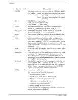
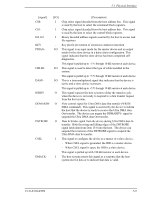
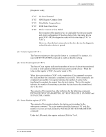
Interface [signal] ENCSEL MSTRRESETDATA 0-15 DIOWSTOP DIORHDMARDY- HSTROBE INTRQ [I/O] I I I I/O I I I I I O [Description] This signal is used to set master/slave using the CSEL signal (pin 28). Pins B and D Open: Sets master/slave using the CSEL signal is disabled. Short: Sets master/slave using the CSEL signal is enabled. MSTR, I, Master/slave setting Pin A, B, C, D open: Master setting Pin A, B Short: Slave setting Reset signal from the host. This signal is low active and is asserted for a minimum of 25 µs during power on. Sixteen-bit bi-directional data bus between the host and the device. These signals are used for data transfer Signal asserted by the host to write to the device register or data port. DIOW- must be negated by the host before starting the Ultra DMA transfer. The STOP signal must be negated by the host before data is transferred during the Ultra DMA transfer. During data transfer in Ultra DMA mode, the assertion of the STOP signal asserted by the host later indicates that the transfer has been suspended. Read strobe signal from the host to read the device register or data port Flow control signal for Ultra DMA data In transfer (READ DMA command). This signal is asserted by the host to inform the device that the host is ready to receive the Ultra DMA data In transfer. The host can negate the HDMARDY- signal to suspend the Ultra DMA data In transfer. Data Out Strobe signal from the host during Ultra DMA data Out transfer (WRITE DMA command). Both the rising and falling edges of the HSTROBE signal latch data from Data 15-0 into the device. The host can suspend the inversion of the HSTROBE signal to suspend the Ultra DMA data Out transfer. Interrupt signal to the host. This signal is negated in the following cases: − assertion of RESET- signal − Reset by SRST of the Device Control register − Write to the command register by the host − Read of the status register by the host − Completion of sector data transfer (without reading the Status register) The signal output line has a high impedance when no devices are selected or interruption is disabled. 5-4 C141-E104-03EN
-
 1
1 -
2
-
3
-
4
-
5
-
6
-
7
-
8
-
9
-
10
-
11
-
12
-
13
-
14
-
15
-
16
-
17
-
18
-
19
-
20
-
21
-
22
-
23
-
24
-
25
-
26
-
27
-
28
-
29
-
30
-
31
-
32
-
33
-
34
-
35
-
36
-
37
-
38
-
39
-
40
-
41
-
42
-
43
-
44
-
45
-
46
-
47
-
48
-
49
-
50
-
51
-
52
-
53
-
54
-
55
-
56
-
57
-
58
-
59
-
60
-
61
-
62
-
63
-
64
-
65
-
66
-
67
-
68
-
69
-
70
-
71
-
72
-
73
-
74
-
75
-
 76
76 -
 77
77 -
 78
78 -
 79
79 -
 80
80 -
 81
81 -
 82
82 -
 83
83 -
 84
84 -
 85
85 -
 86
86 -
87
-
88
-
89
-
90
-
91
-
92
-
93
-
94
-
95
-
96
-
97
-
98
-
99
-
100
-
101
-
102
-
103
-
104
-
105
-
106
-
107
-
108
-
109
-
110
-
111
-
112
-
113
-
114
-
115
-
116
-
117
-
118
-
119
-
120
-
121
-
122
-
123
-
124
-
125
-
126
-
127
-
128
-
129
-
130
-
131
-
132
-
133
-
134
-
135
-
136
-
137
-
138
-
139
-
140
-
141
-
142
-
143
-
144
-
145
-
146
-
147
-
148
-
149
-
150
-
151
-
152
-
153
-
154
-
155
-
156
-
157
-
158
-
159
-
160
-
161
-
162
-
163
-
164
-
165
-
166
-
167
-
168
-
169
-
170
-
171
-
172
-
173
-
174
-
175
-
176
-
177
-
178
-
179
-
180
-
181
-
182
-
183
-
184
-
185
-
186
-
187
-
188
-
189
-
190
-
191
-
192
-
193
-
194
-
195
-
196
-
197
-
198
-
199
-
200
-
201
-
202
-
203
-
204
-
205
-
206
-
207
-
208
-
209
-
210
-
211
-
212
-
213
-
214
-
215
-
216
-
217
-
218
-
219
-
220
-
221
-
222
-
223
-
224
-
225
-
226
-
227
-
228
-
229
-
230
-
231
-
232
 |
 |
