Ganz Security HSW-H37-4 ZN1-V4FN4 (IP Pinhole) Camera Manual - Page 16
Function, Specifications
 |
View all Ganz Security HSW-H37-4 manuals
Add to My Manuals
Save this manual to your list of manuals |
Page 16 highlights
PixelPro GXi Series ZN1-V4FN3/FN4 Installation Guide DI (Sensor) - For connecting a device such as a PIR and a door/window sensor. Do the electrical wiring correctly referring to the following information. DI Function C Ground 1 Input Specifications 0 to 5 VDC Max load: 50mA Internal +3.3V Output of DI Sensor + - Internal Output of DI Sensor + - COM COM - + Relay Type Voltage Type Then, the connected device can be activated via its webpage. Go to "6. CONFIGURATION" for more details for its setting. Camera connector 2) Connect the camera unit to the main unit by inserting the camera's DIN connector to the camera's connector on the main unit by placing the arrow mark on the camera's DIN connector upward like the image below. 06-2014-B 16
-
 1
1 -
2
-
3
-
4
-
5
-
6
-
7
-
8
-
9
-
10
-
 11
11 -
 12
12 -
 13
13 -
 14
14 -
 15
15 -
 16
16 -
 17
17 -
 18
18 -
 19
19 -
 20
20 -
 21
21 -
22
-
23
-
24
-
25
-
26
-
27
-
28
-
29
-
30
-
31
-
32
-
33
-
34
-
35
 |
 |
PixelPro GXi Series
ZN1-V4FN3/FN4 Installation Guide
06-2014-B
16
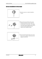
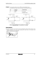
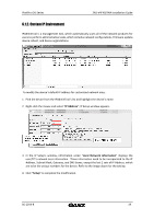
DI (Sensor)
–
For connecting a device such as a PIR and a door/window sensor.
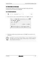
Do the electrical wiring correctly referring to the following information.
DI
Function
Specifications
C
Ground
1
Input
0 to 5 VDC
Max load: 50mA
Then, the connected device can be activated via its webpage.
Go to
“
6. CONFIGURATION
”
for more details for its setting.
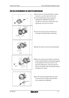
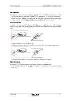
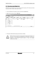
Camera connector
2)
Connect the camera unit to the main unit by inserting the camera
’
s DIN connector to the
camera
’
s connector on the main unit by placing the arrow mark on the camera
’
s DIN
connector upward like the image below.
+3.3V
DI
COM
DI
COM
+
-
Relay Type
Voltage Type
+
-
Output of
Sensor
Output of
Sensor
Internal
Internal
+
-