Garmin GI-205 Pilots Guide - Page 8
Decision Height Alerts, 6 Trend Indicator
 |
View all Garmin GI-205 manuals
Add to My Manuals
Save this manual to your list of manuals |
Page 8 highlights
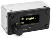
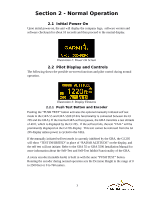
height value will blink for two seconds and then stay highlighted as long as the currently displayed radar altitude is below (or up to 50 ft above) the selected decision height. Illustration 5: Decision Height Highlighted 2.5 Decision Height Alerts The decision height alerts are activated if the currently displayed radar altitude crosses below the set decision height. The alert is annunciated both visually and aurally. The options for the visual alert are described in the above section. The GI 205 also plays an aural alert heard as a "minimums, minimums" annunciation in a male or female voice or a 1 kHz tone for two seconds, depending upon the "DH AURAL ALERT" configuration selection during installation. As stated in the above section, once the visual alert is active it remains active until the displayed radar altitude reaches 50 feet above the set decision height, with one exception. If the decision height is set to 0 feet (or meters), and if the displayed radar altitude also becomes 0 feet (or meters), the alert becomes inactive after 1 second. 2.6 Trend Indicator An altitude trend indicator is optionally displayed on the right side of the radar altitude display. The trend indicator attempts to calculate the radar altitude trend (climb or descent and relative magnitude thereof) based upon incoming altitudes from the GRA. It consists of an up/down arrow and a maximum of five associated bars. Positive vertical trend (climb) is indicated by an up arrow and associated bars below it. Negative vertical trend (descent) is indicated by a down arrow and associated bars above it. The trend indicator maps the arrows and bars to six trend points based upon the "MAX TREND SCALE" value configured during installation (full deflection of the trend indicator). The trend indicator displays only the up or down arrow when vertical trend reaches 8% of the "MAX TREND SCALE" selection. It then adds a successive bar below/above the arrow when vertical trend reaches 20%, 40%, 60%, 80% and 100% of the configured "MAX TREND SCALE" value. The altitude trend indicator can be hidden by disabling the "TREND INDICATOR" configuration option during installation. The trend indicator display is also temporarily disabled when the "PUSH TEST" button is depressed and the GRA enters the manually initiated self test mode. 5
-
 1
1 -
2
-
 3
3 -
 4
4 -
 5
5 -
 6
6 -
 7
7 -
 8
8 -
 9
9 -
 10
10 -
 11
11
 |
 |
