Garmin GPSMAP 276C Owner's Manual - Page 111
Installation Information, Connecting the Power/Data Cable
 |
UPC - 753759044138
View all Garmin GPSMAP 276C manuals
Add to My Manuals
Save this manual to your list of manuals |
Page 111 highlights
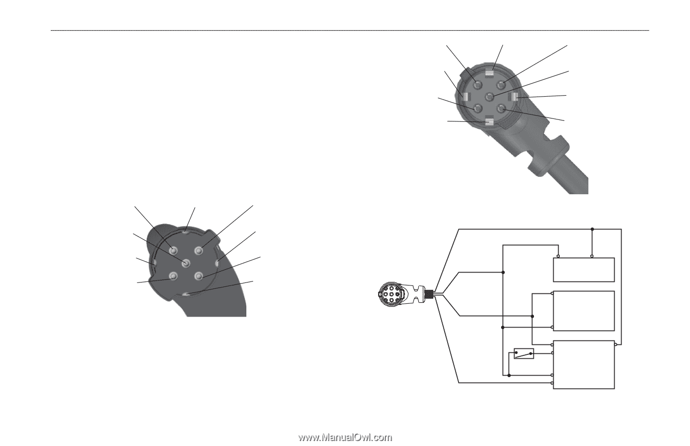
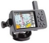
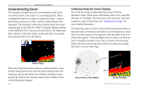
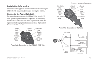
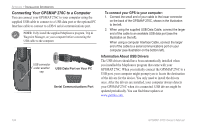
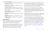
Installation Information This section of the Appendix provides information on connecting the GPSMAP 276C to auxiliary devices and removing the antenna. Connecting the Power/Data Cable The power/data cable connects the GPSMAP 276C to an 11-35 VDC system and provides interface capabilities for connecting external devices. The color code in the diagram below and to the right indicates the appropriate harness connections. Replacement fuse is a 3AG - 1.5 Amp fuse. Ground Black Alarm White Voice (+) Brown Data In 1 Yellow Voice (-) Orange Data Out 1 Blue Data In 2 Green Power Red Data Out 2 Violet Power/Data Connector on the GPSMAP 276C Unit GPSMAP 276C Owner's Manual Data Out 1 Blue Data In 2 Green Power Red Data Out 2 Violet Appendix > Installation Information Voice (-) Orange Ground Black Alarm White Voice (+) Brown Data In 1 Yellow Power/Data Connector on the Cable Red: Power Black: Ground (-) (+) 11-35 VDC Blue: Data Out Yellow: Data In RXD + Autopilot/ NMEA Device RXD - Switch White/Blue (+) Orange Closed - On, Open - Off (-) GSD 21 Sounder White/Brown 103
-
 1
1 -
2
-
3
-
4
-
5
-
6
-
7
-
8
-
9
-
10
-
11
-
12
-
13
-
14
-
15
-
16
-
17
-
18
-
19
-
20
-
21
-
22
-
23
-
24
-
25
-
26
-
27
-
28
-
29
-
30
-
31
-
32
-
33
-
34
-
35
-
36
-
37
-
38
-
39
-
40
-
41
-
42
-
43
-
44
-
45
-
46
-
47
-
48
-
49
-
50
-
51
-
52
-
53
-
54
-
55
-
56
-
57
-
58
-
59
-
60
-
61
-
62
-
63
-
64
-
65
-
66
-
67
-
68
-
69
-
70
-
71
-
72
-
73
-
74
-
75
-
76
-
77
-
78
-
79
-
80
-
81
-
82
-
83
-
84
-
85
-
86
-
87
-
88
-
89
-
90
-
91
-
92
-
93
-
94
-
95
-
96
-
97
-
98
-
99
-
100
-
101
-
102
-
103
-
104
-
105
-
 106
106 -
 107
107 -
 108
108 -
 109
109 -
 110
110 -
 111
111 -
 112
112 -
 113
113 -
 114
114 -
 115
115 -
 116
116 -
117
-
118
-
119
-
120
-
121
-
122
-
123
-
124
-
125
-
126
-
127
-
128
-
129
-
130
-
131
-
132
-
133
-
134
 |
 |