GE 60-774 Installation Instructions - Page 4
Wiring the Module - com
 |
UPC - 046188091768
View all GE 60-774 manuals
Add to My Manuals
Save this manual to your list of manuals |
Page 4 highlights
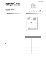
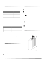
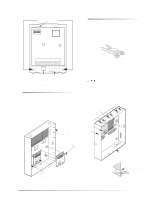
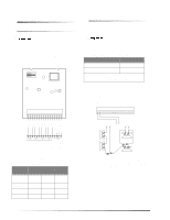
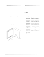
Wiring the Module Wiring the Module To Wire the Module to a Panel To Wire Detectors to the Module Follow the maximum zone input wire length (run) guidelines in Table 5 based on the type of wire used. t On Advent panels, the BUS 1 and BUS 2 headers must be used only for fire or burglary applications. Do not mix fire and burglary bus devices on either header. 1. Make sure the panel AC power is turned off or removed, and the panel backup battery(s) are disconnected. 2. Wire the module to the panel as shown in Figure 7 and explained in Table 4. t For Advent UL-864 Listed Installations, all inputs must be dedicated to either fire or burglary applications. Do not mix fire and burglary on any module in any partition for these installations. Table 5. Zone Input Wire Runs Gauge Max. Wire Run* 18 750 Feet 22 300 Feet *Wire run based on 10 ohms maximum wire and device resistance including 2.0K ohm EOL resistor. 1. Figure 8 shows an example of how to connect up to eight normally closed (N/C) or normally open (N/O) intrusion circuits to the module. ZONE COM ZONE 1 GND (BLK) BUS B (WHT) BUS A (GRN) +12 VDC (RED) ZONE 8 ZONE COMMON ZONE 7 ZONE 6 ZONE COMMON ZONE 5 ZONE 4 ZONE COMMON ZONE 3 ZONE 2 ZONE COMMON ZONE 1 1 2 3 4 5 6 7 8 9 10 11 12 13 14 15 16 TO PANEL TO ZONE SUPERBUS TERMINALS INPUT OR CONNECTOR DEVICE (SEE TABLE) (SHARED COMMONS) 9712G03A.DSF Figure 7. General Module Wiring Table 4. SuperBus Module/Panel Wiring Module Advent* Terminals UltraGard 13 Red 12 (+12VDC) 14 (BUS A) Green 13 15 (BUS B) White 14 16 (GND) Black 15 Concord 4 5 6 3 * Panel SuperBus device connector wiring harness. (Connect to either panel connector.) 4 1 2 3 4 5 6 7 8 9 10 11 12 13 14 15 16 UL-LISTED NORMALLY CLOSED (N/C) CONTACTS IN SERIES < OR > UL-LISTED NORMALLY OPEN (N/O) CONTACTS IN PARALLEL 2.0K OHM EOL RESISTOR 49-467 (INSTALL AT LAST DEVICE) 9712G04A.DSF Figure 8. Connecting N/C and N/O Intrusion Circuits to the Module
-
 1
1 -
 2
2 -
 3
3 -
 4
4 -
 5
5 -
 6
6 -
 7
7 -
 8
8
 |
 |