GE 60-803-04 Installation Instructions - Page 4
Mounting the Touchpad, Setting Touchpad Unit Numbers, Power Up and Bus Communication
 |
UPC - 046188088645
View all GE 60-803-04 manuals
Add to My Manuals
Save this manual to your list of manuals |
Page 4 highlights
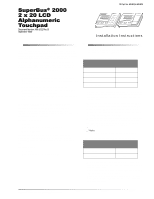
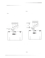
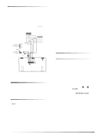
Mounting the Touchpad 3. Insert the touchpad wiring harness connector onto the pins located on the rear of the unit. Make sure the yellow wires are to the left (see Figure 5). TO ADDITIONAL SUPERBUS TOUCHPADS AND/OR MODULES PANEL SUPERBUS WIRING HARNESS 49-462 BLACK (GND) WHITE (BUS B) GREEN (BUS A) RED (+12 VDC) OPTIONAL N/O SWITCH WITH MAGNET SPLICE 2K OHM EOL RESISTOR Connect Shield to Earth Ground OPTIONAL N/C SWITCH WITH MAGNET SHIELDED CABLE YELLOW NOT USED TOUCHPAD WIRING HARNESS 49-430 TAB SLOT(3) 8543109C.DSF Figure 5. Wiring the Touchpad to Advent Panels Mounting the Touchpad 1. Align the slots on the touchpad with the slots on the back-plate. Insert the mounting tabs into the mounting slots and press the keypad toward the wall/gang box. 2. Tighten the two bottom screws. Setting Touchpad Unit Numbers Note In multiple partition systems all new touchpads default to partition 1. To change partition assignment please see specific panel Installation Instructions. All partitions must be disarmed before entering program mode. Panels automatically assign or learn the unit numbers of each bus device upon power up or entering programming mode. SuperBus 2000 panels (Advent panels and Concord panels with software version 2.0 or newer) automatically assign different unit numbers to each SuperBus 2000 module. SuperBus panels (UltraGard panels and Concord panels with software versions 1.0-1.6) do not automatically assign different unit numbers to each SuperBus 2000 module. For these panels, alphanumeric touchpads default to 001. If desired or necessary, the unit number must be manually changed. Guidelines for Assigning Alphanumeric Touchpad Unit Numbers (Concord panels with software versions 1.0-1.6 and UltraGard panels) Use the following guidelines to avoid communication conflicts between bus devices and the panel: Always start with one touchpad connected to the panel and make sure it is working properly before connecting additional touchpads. Whenever possible, such as in new installations, assign alphanumeric touchpad unit numbers before beginning all other panel programming. Other bus devices with device unit number DIP switches (ESM, HIM, etc.) must be set to the desired unit number before applying power and entering program mode. Power Up and Bus Communication Powering Up UltraGard Panels First Touchpad 1. Disconnect all bus device wiring from the panel except for the touchpad location closest to the panel. 2. Verify that all wiring at the panel and touchpad wiring harness is correct. 3. With the panel power switch off, connect the panel battery and plug in the panel AC power transformer. 4. Set the panel RUN/PROGRAM switch to RUN. 5. Turn on the panel power switch. 6. Put the touchpad into the manual configuration mode by pressing and holding the touchpad D and 6 buttons until the display shows DA 001 (unit number 001). 7. Set the panel RUN/PROGRAM switch to PROGRAM and the display should read PROGRAM MODE. 8. Verify correct operation by pressing STATUS or BYPASS. The display should show a different menu item for each button pressed. If your installation only calls for one alphanumeric touchpad, you may proceed with other system programming. If you have more alphanumeric touchpads to connect and assign device addresses, use the following procedure before proceeding with any other system programming. 4 SuperBus® 2000 2 x 20 LCD Alphanumeric Touchpad
-
 1
1 -
 2
2 -
 3
3 -
 4
4 -
 5
5 -
 6
6 -
 7
7 -
 8
8
 |
 |